Method for driving matrix displays

a matrix display and display technology, applied in the field of driving matrix displays, can solve the problems of increasing power consumption, short application time of the operating current, and significant reduction of the lifetime of the oled, so as to improve the performance of any matrix display and increase the life of the oled display

Inactive Publication Date: 2013-06-04
UNIV DES SAARLANDES +2
View PDF10 Cites 1 Cited by
  • Summary
  • Abstract
  • Description
  • Claims
  • Application Information

AI Technical Summary

Benefits of technology

[0017]The object of the present technology is to propose a method for driving matrix displays corresponding to the type mentioned at the start, with which the lifetime of the OLED display can be increased or the performance of any matrix display can be improved.
[0018]This object is achieved according to the present technology in that the row addressing time ti for each row i is determined as a function of the maximum brightness Dimax of all the columns j of the row i. The row addressing time ti can thereby be selected to be less than or equal to a constant row addressing time tL which is produced when each row of the matrix display is addressed for so long that a maximum pixel brightness Dmax could be achieved with the impressed operating current. The row addressing time ti according to the present technology therefore corresponds to the constant row addressing time tL multiplied by the ratio of the maximum brightness Dimax of the pixels in all the columns j of the row i to the maximum possible pixel brightness Dmax in the entire matrix display. The maximum pixel brightness Dmax is defined as the light intensity (brightness) in one pixel ij, which is achieved when the operating current I0 is applied to the pixel during the constant row addressing time tL. This has the effect that the time sum TSum of the row addressing times ti over the number n of all the rows is less than or equal to the total time TFrame for activating all n rows, which activation is given by n×the constant row addressing time tL. If the operating current I0 is constant, the total time for driving the matrix display can therefore be reduced according to the present technology to the time sum TSum<TFrame of the row addressing times. This makes possible for example a higher frame rate and increases the achievable performance of a matrix display.
[0019]Since the light intensity of a pixel ij in the first approximation is proportional to the charge which is impressed in a pixel ij, i.e. is proportional to the product of the row addressing time ti and the operating current, the dependence of the row addressing time ti on the maximum brightness over the columns of a row can also be used to reduce the operating current. To this end, the total time TFrame for activating all the rows i can be kept constant so that the sum of the row addressing times t′i over all rows n corresponds to the total time TFrame. The row addressing times t′i are therefore extended according to this variant of the inventive method, so that their sum is equal to the total time TFrame. At the same time the operating current I0 can according to the present technology be reduced by the ratio of the time sum TSum of the (absolutely necessary) row addressing times ti of all the rows n to the total time (TFrame) for activating all the rows with the constant row addressing time tL to the operating current I1. The light intensity of the individual pixels does not change because the product of the row addressing time and the operating current ti*I0=t′i*I1 remains constant. In the case of OLEDs, the quantum efficiency η in a lower operating current range is as a rule greater than with a higher operating current. The operating current I1 can therefore be additionally reduced by the ratio of the quantum efficiencies η(I1) / η(I0). For the sake of simplicity, the row addressing time t′i (which is extended or standardised to TFrame) is also referred to as t′i below.

Problems solved by technology

In this case just the application time of the operating current is very short.
The high operating current can however lead to a significant reduction in the OLED lifetime.
In order to achieve the necessary high operating current, the voltage at the OLEDs must also be increased, as a result of which the power consumption increases and the efficiency is reduced.
This increased power loss not only discharges the rechargeable or disposable battery more quickly, but also makes the display warmer, as a result of which the lifetime is likewise reduced.
Active matrix driving (TFT backplane) however requires significant additional costs for an OLED display.

Method used


Image

  • Method for driving matrix displays
  • Method for driving matrix displays
  • Method for driving matrix displays

Examples


Embodiment Construction

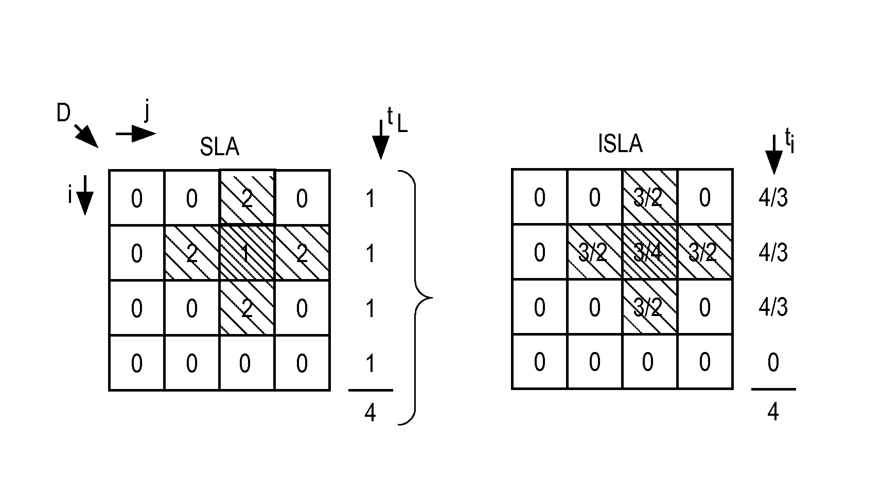
[0057]FIG. 1 schematically shows a matrix display D which is made up of four rows i and four columns j. The matrix display D correspondingly has a total of sixteen pixels ij which are to have the brightness Dij. Each pixel ij is represented by a square in which the digital brightness value Dij is entered as a number. The brightness value “0” stands for a dark pixel ij, the brightness value “1” stands for a dimly luminous pixel ij and the brightness value “2” stands for a brightly luminous pixel.

[0058]FIG. 1a therefore shows a matrix display D on which a cross can be seen, with a dim centre in the pixel ij=23 and four bright pixels at its arcs. In conventional single-line addressing (SLA) the matrix display D is driven in such a manner that the rows one to four are activated consecutively in each case for a constant row addressing time tL which is given by the value “1” in arbitrary units. While the first row is being activated, an operating current I is applied to the third column, ...


PUM


Abstract

A method is described for driving matrix displays which are made up of a plurality of lines with individual pixels, which lines are configured as rows and columns, wherein individual lines are driven selectively by rows being activated for a defined row addressing time and an operating current or a corresponding voltage being applied to the columns in correlation with the activated row corresponding to the desired brightness in the pixels. In order to improve the performance of the display, the row addressing time for each row is determined as a function of the maximum brightness of all the columns of the row.

Description

RELATED APPLICATIONS[0001]This application is a continuation of International Application No. PCT / EP2006 / 012362 (International Publication Number WO / 2007 / 079947), having an International filing date of Dec. 21, 2006 entitled “Verfahren Zur Ansteuerung Von Matrixanzeigen” (“Method For Triggering Matrix Displays”). International Application No. PCT / EP2006 / 012362 claimed priority benefits, in turn, from German Patent Application No. 10 2005 063 159.2, filed Dec. 30, 2005. International Application No. PCT / EP2006 / 012362 and German Application No. 10 2005 063 159.2 are hereby incorporated by reference herein in their entireties.FEDERALLY SPONSORED RESEARCH OR DEVELOPMENT[0002][Not Applicable]MICROFICHE / COPYRIGHT REFERENCE[0003][Not Applicable]BACKGROUND OF THE INVENTION[0004]The presently described technology relates to a method for driving matrix displays which are made up of a plurality of lines with individual pixels, which lines are configured as rows and columns, wherein individual ...

Claims


Application Information

Patent Timeline
Patent Type & Authority Patents(United States)
IPC IPC(8): G09G5/10
CPCG09G3/2014G09G3/2081G09G3/3216G09G3/3266G09G5/18G09G2310/0205G09G2360/16
Inventor XU, CHIHAOWAHL, JURGENEISENBRAND, FRIEDRICHKARRENBAUER, ANDREASSOH, KIAN MINHITZELBERGER, CHRISTOPH
Owner UNIV DES SAARLANDES
Why Eureka
Try Eureka