Supporting arrangement

a support arrangement and arrangement technology, applied in the direction of ballastways, railway tracks, railway routes, etc., can solve the problems of system being difficult to implement and lack of solidity, so as to avoid interruption of railway traffic, reduce the duration of the caisson moving process, and reduce the completion time of the whole work

Active Publication Date: 2013-06-11
PETRUCCO
View PDF3 Cites 2 Cited by
  • Summary
  • Abstract
  • Description
  • Claims
  • Application Information

AI Technical Summary

Benefits of technology

[0024]Another object of the invention is to avoid the installation of the longitudinal shoring assemblies which are at present used, assembly and disassembly of which is relatively time-consuming.
[0025]Another object of the invention is to provide a self-supporting shoring arrangement which avoids interruption of the railway traffic during assembly and disassembly thereof.
[0026]Yet another object of the invention is to reduce the duration of the process for moving the caisson since the railway track is self-supporting and the installation of transverse supports above the top part of the caisson is not required. As a result, the completion times for the whole work are reduced.

Problems solved by technology

In order to carry out infrastructures such as underpasses under the railway tracks a number of rails are arranged in a parallel arrangement with respect to the railway track, the rails being inferiorly connected to each other by a transversal rail section, this system being nevertheless hard to implement and lacking in solidity.

Method used


Image

  • Supporting arrangement
  • Supporting arrangement
  • Supporting arrangement

Examples


Embodiment Construction

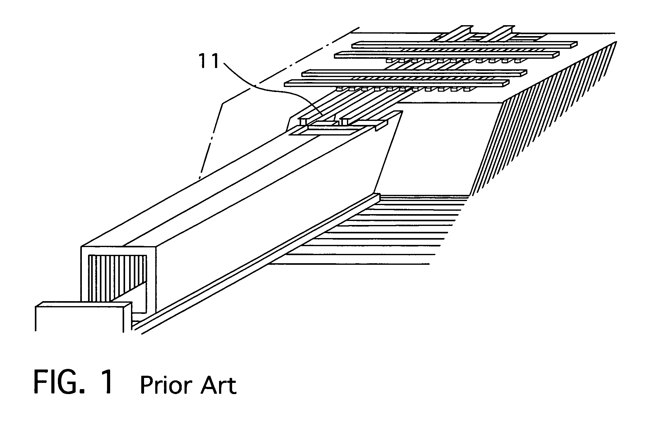
[0036]Below, with reference to FIG. 1, a process for inserting a caisson is shown, it being possible to see the transverse support 11, i.e. fastened sections 11 which have the function of supporting the associated track and transmitting the loads of the rolling stock travelling on the rails and creating a surface below which the caisson is slid.

[0037]One of the advantages of the present invention consists in the elimination of the fastened sections 11 of metal beams, which ensures at all times correct positioning of the railway track, below which construction of a passage below the railway is performed.

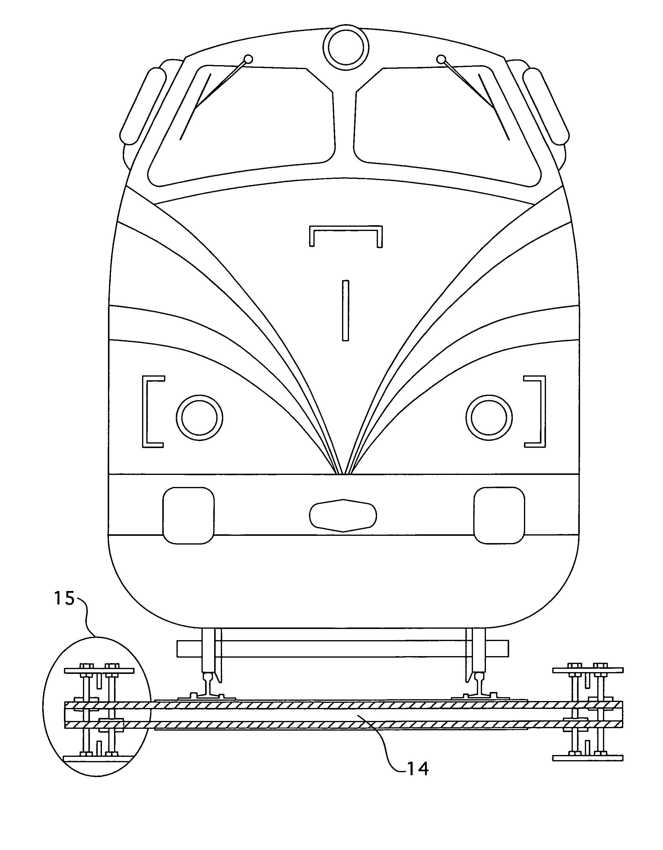
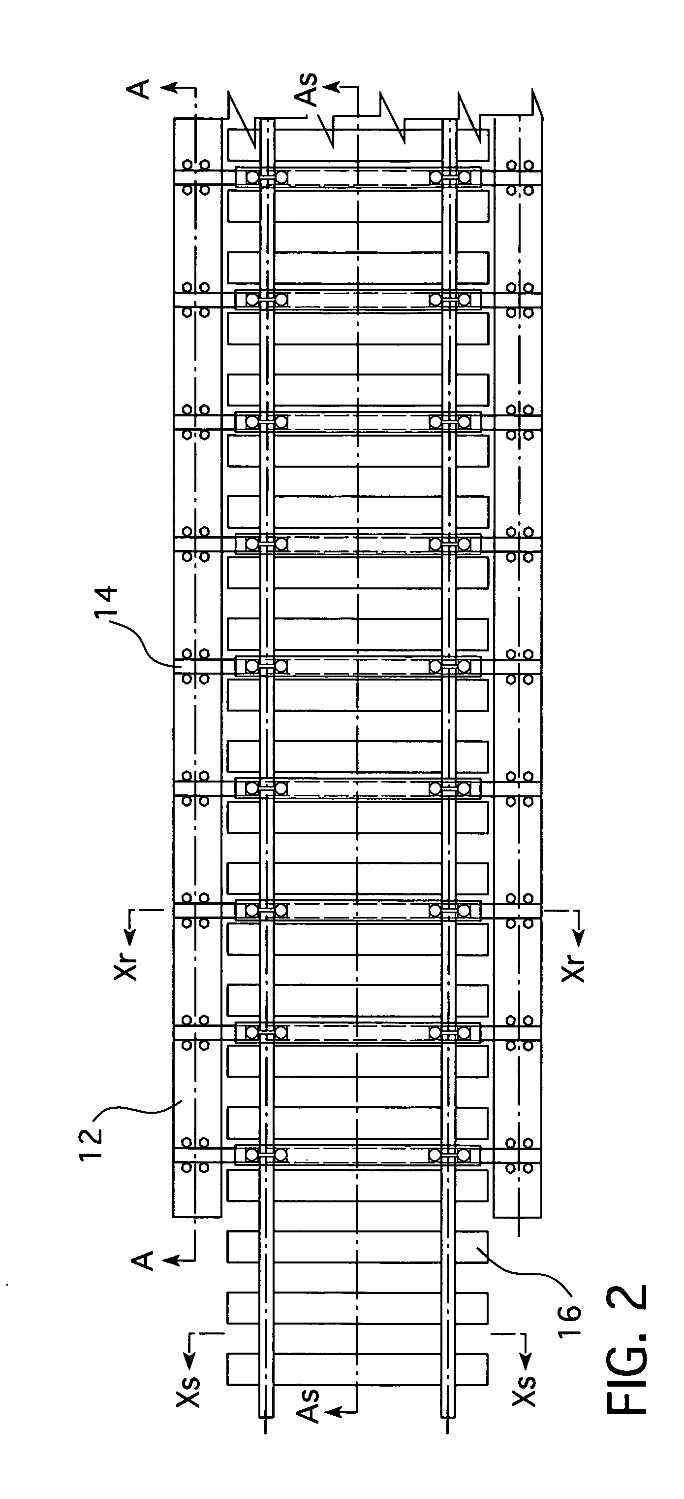
[0038]With reference now to FIG. 2, the shoring arrangement according to the invention comprises first metal shoring beams 12, a first longitudinal metal beam 12 arranged parallel to a line 17 of the track on the outer side of the track line 17, that is, between the two track lines 17 there is no longitudinal beam 12 installed.

[0039]The set of first longitudinal beams 12 is braced by ...


PUM


Abstract

Supporting arrangement intended to be arranged in a shoring zone of railway lines (17), where at least first longitudinal metal beams (12) are arranged parallel to a line of the track on the outer side of each track line (17) so that they are braced by at least one second perpendicular metal beam (14) with a length less than that of the first longitudinal beams (12) and the joining of each longitudinal beam (12) to one end of the perpendicular beam (14) is performed by means of a mechanical fixing means (15).

Description

FIELD OF THE INVENTION[0001]The present invention relates, generally, to a method for carrying out construction work underneath roadways or railways without interrupting the traffic.[0002]More specifically, the present invention relates to a method for eliminating road and railway line intersections by providing a bottom passage structure outside of its final location and arranging it in position by means of displacement or thrusting of inserted caisson elements, while ensuring continuous communication above the intersection.STATE OF THE ART[0003]It is known in the state of the art to eliminate an intersection level crossing by means of the prefabricated construction of a bottom passage underneath the intersection and its installation using the thrusting or inserted caisson technique.[0004]Elimination of the level crossing at an intersection comprises at least the following operations: manufacture and arrangement of the caisson, provision of a receiving surface, after construction o...

Claims


Application Information

Patent Timeline
Patent Type & Authority Patents(United States)
IPC IPC(8): E01B3/00
CPCE01B1/00E01B2/00E01B3/22
Inventor STEFANUTTI, RINO
Owner PETRUCCO
Why Eureka
Try Eureka