Belt-drive CVT

a belt drive and cvt technology, applied in the direction of instruments, mechanical equipment, gearing, etc., can solve the problems of limited installation position of the rotation sensor and reduce layout flexibility, and achieve the effect of reducing layout flexibility

Active Publication Date: 2013-06-11
JATCO LTD +1
View PDF37 Cites 18 Cited by
  • Summary
  • Abstract
  • Description
  • Claims
  • Application Information

AI Technical Summary

Benefits of technology

[0003]In such a belt-drive CVT in JP2002-295613, however, since the detection teeth are formed at the stationary pulley, an installation position of the rotation sensor is limited to some extent, and this reduces layout flexibility.
[0004]For this problem, it is therefore an object of the present invention to provide a belt-drive CVT that is capable of increasing the layout flexibility.

Problems solved by technology

In such a belt-drive CVT in JP2002-295613, however, since the detection teeth are formed at the stationary pulley, an installation position of the rotation sensor is limited to some extent, and this reduces layout flexibility.

Method used


Image

  • Belt-drive CVT
  • Belt-drive CVT
  • Belt-drive CVT

Examples


embodiment 1

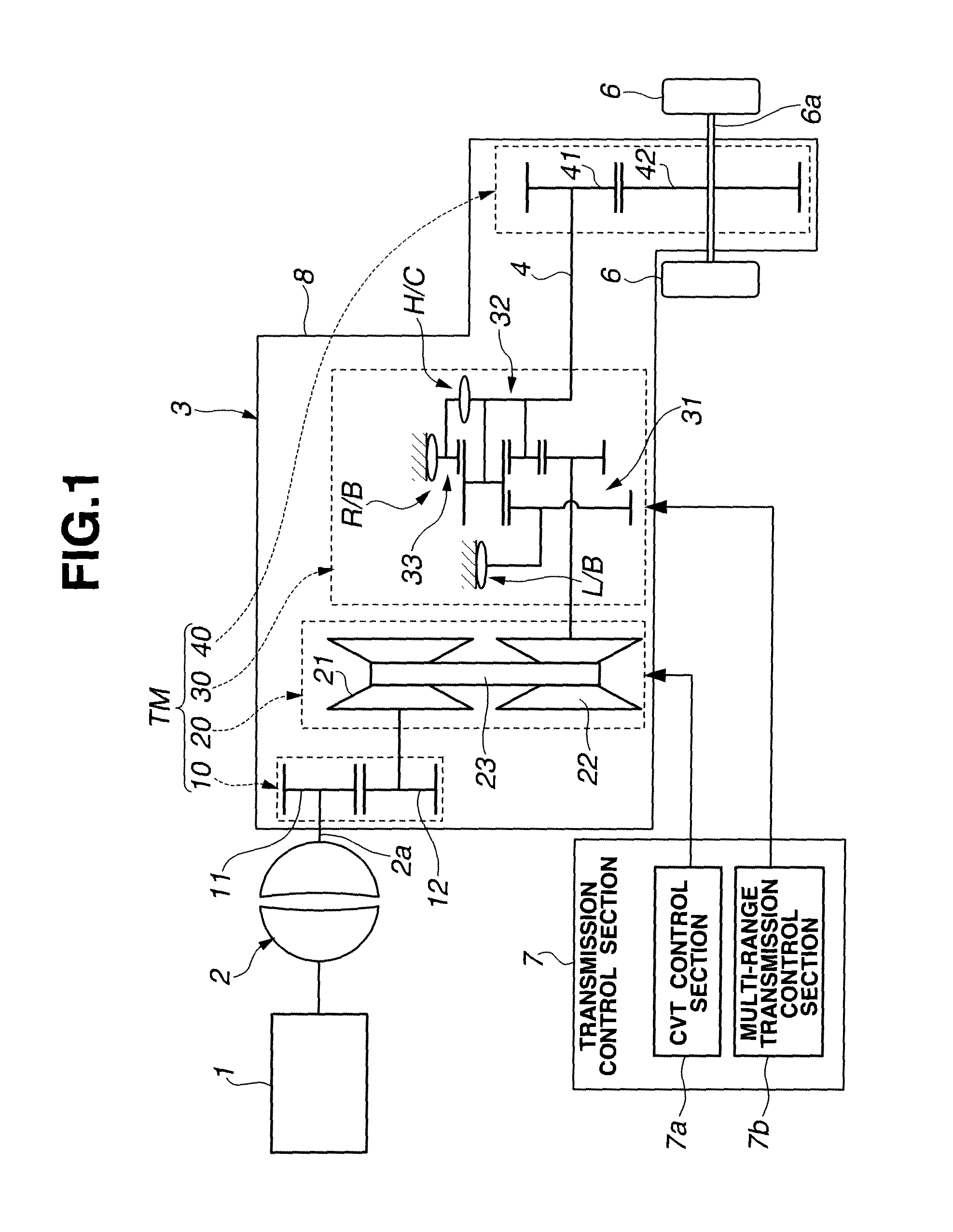
[0015]First, a system in the present invention will be explained. A power train shown in FIG. 1 has an engine 1 that is a drive source, a torque converter 2 that is connected with and driven by the engine 1, an automatic transmission (a belt-drive CVT (continuously variable transmission)) 3 that is connected with and driven by the torque converter 2, and wheels 6, 6 to which a power is transmitted and outputted from the automatic transmission 3 through a drive shaft 6a. The automatic transmission 3 is controlled by a transmission control section 7 having a continuously variable transmission control section (a CVT control section) 7a that controls an after-mentioned continuously variable transmission mechanism (CVT mechanism) 20 and a multi-range (or a geared) transmission control section 7b that controls an after-mentioned multi-range (or geared) transmission mechanism 30.

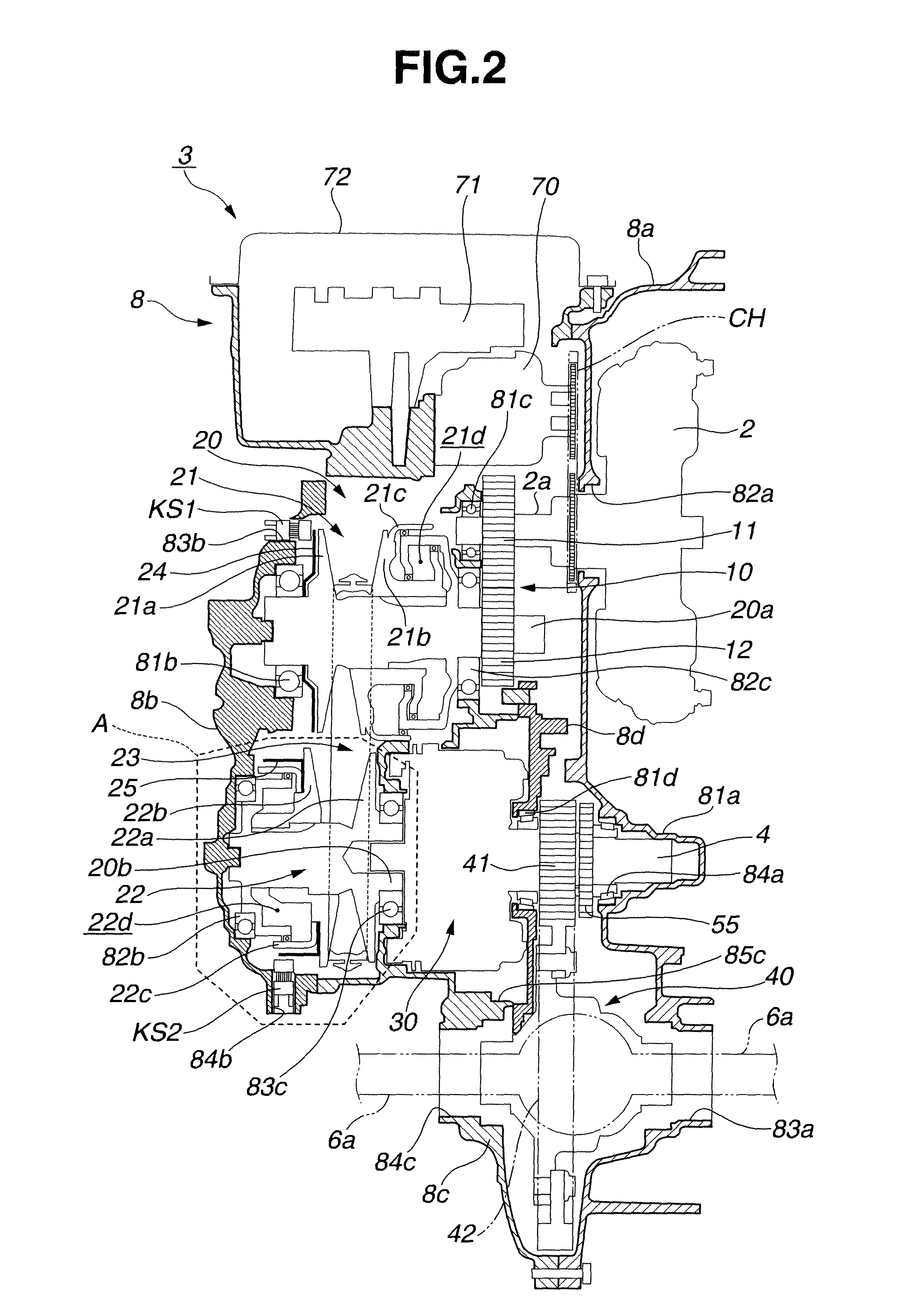
[0016]The automatic transmission 3 has a transmission mechanism TM that is housed in a transmission casing (a ho...


PUM


Abstract

A belt-drive CVT includes a pair of pulleys, each of which has a stationary pulley and a movable pulley that moves toward or away from the stationary pulley in an axial direction of the pulley, a belt that is wound around the pair of pulleys and a rotation state detecting device for detecting rotation of the pulley. The rotation state detecting device has a tone wheel that rotates integrally with the pulley and a sensor that faces the tone wheel. The tone wheel has a cylinder portion that extends along a moving direction of the movable pulley. The cylinder portion is provided with a plurality of detection portions which are arranged at regular intervals in a circumferential direction throughout an entire circumference of the cylinder portion and which extend along the moving direction of the movable pulley.

Description

BACKGROUND OF THE INVENTION[0001]The present invention relates to a belt-drive CVT (continuously variable transmission) having a rotation state detecting device.[0002]In a related art, to detect a rotation state (such as the number of revolutions and a rotation speed) of a pulley that has a belt pressed between a stationary pulley (a stationary sheave) and a movable pulley (a movable sheave), a belt-drive CVT in which an annular protruding portion having detection teeth for a rotation sensor is formed on a back surface of an outer circumferential portion of the stationary pulley has been known. For example, such a belt-drive CVT is disclosed in Japanese is Patent Provisional Publication No. 2002-295613 (hereinafter is referred to as “JP2002-295613”).SUMMARY OF THE INVENTION[0003]In such a belt-drive CVT in JP2002-295613, however, since the detection teeth are formed at the stationary pulley, an installation position of the rotation sensor is limited to some extent, and this reduces ...

Claims


Application Information

Patent Timeline
Patent Type & Authority Patents(United States)
IPC IPC(8): F16H59/00F16H61/00
CPCF16H9/18F16H59/38G01P3/443F16H37/022F16H2037/023
Inventor KAJIGAYA, AKIRAKAWAGOSHI, TOMOOIMAI, TAKAHIROIWASAWA, TAKUYAKAWANISHI, DAISUKE
Owner JATCO LTD
Why Eureka
Try Eureka