Apparatus and method for measuring displacements of displaceable members

a technology of displaceable parts and apparatus, which is applied in the direction of measuring devices, instruments, and converting sensor output, etc., can solve the problems of additional cost of encoders, limited life of batteries, and use of batteries

Active Publication Date: 2013-06-11
YASKAWA EURO TECH
View PDF4 Cites 3 Cited by
  • Summary
  • Abstract
  • Description
  • Claims
  • Application Information

AI Technical Summary

Benefits of technology

[0024]As will be described more particularly below, the apparatus and method of the present invention as briefly described above enable measuring the displacement of a displaceable member in a manner which does not require a battery, which uses standard electronic devices, and which is relatively insensitive to vibrations.
[0025]Further features and advantages of the invention will be apparent from the description below.

Problems solved by technology

However the use of battery has a number of drawbacks.
Thus, batteries have a limited life time.
Moreover, replacing a battery without losing the recorded turn counting requires special circuitry, for example a large capacitor, to back up the recorded data during the battery replacement, which circuitry results in additional cost of the encoder.
Further, batteries tolerate a limited range of temperatures, and therefore where the encoders are to be used in high temperature environments, the battery cannot be placed inside the encoder.
U.S. Pat. No. 5,565,769 and U.S. Pat. No. 5,714,882 describe systems that are able to count and register the number of turns of a shaft without a battery; however, these systems are sensitive to vibrations.
U.S. Pat. No. 6,628,741B1 describes apparatus to implement a turns counter without a battery by using a reed relay; however reed relays are sensitive to vibrations, have a limited life time, and can be damaged or destroyed in case of high accelerations.
Another drawback is that the amount of energy produced in order to count and store the number of turns is very small, which limits the system to the use of ferroelectric memories; unfortunately, these memories are not available in small sizes, and this again limits their application in encoders.
Similar problems are involved in linear encoders for measuring linear displacements of a displaceable member.

Method used


Image

  • Apparatus and method for measuring displacements of displaceable members
  • Apparatus and method for measuring displacements of displaceable members
  • Apparatus and method for measuring displacements of displaceable members

Examples


Embodiment Construction

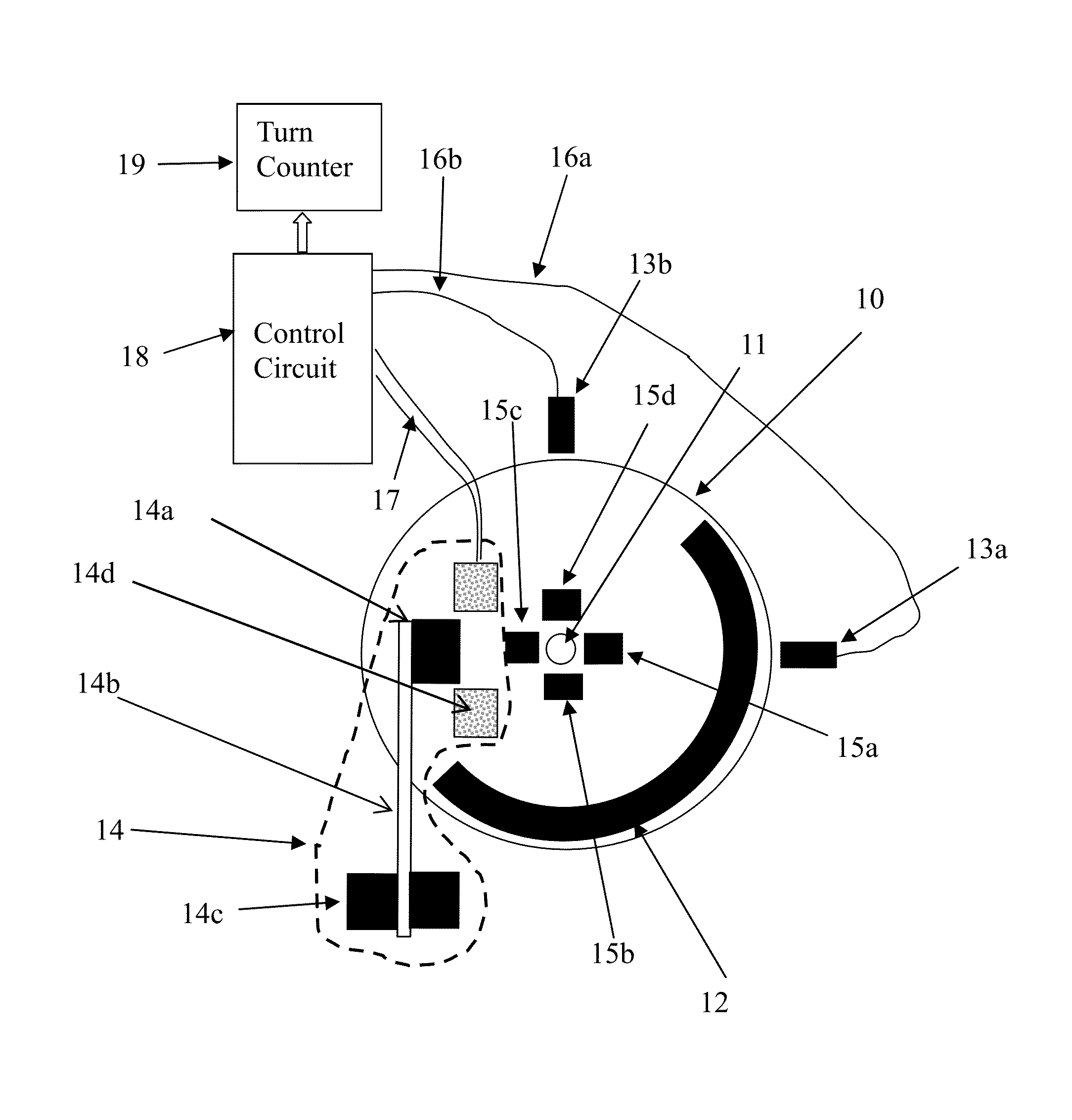
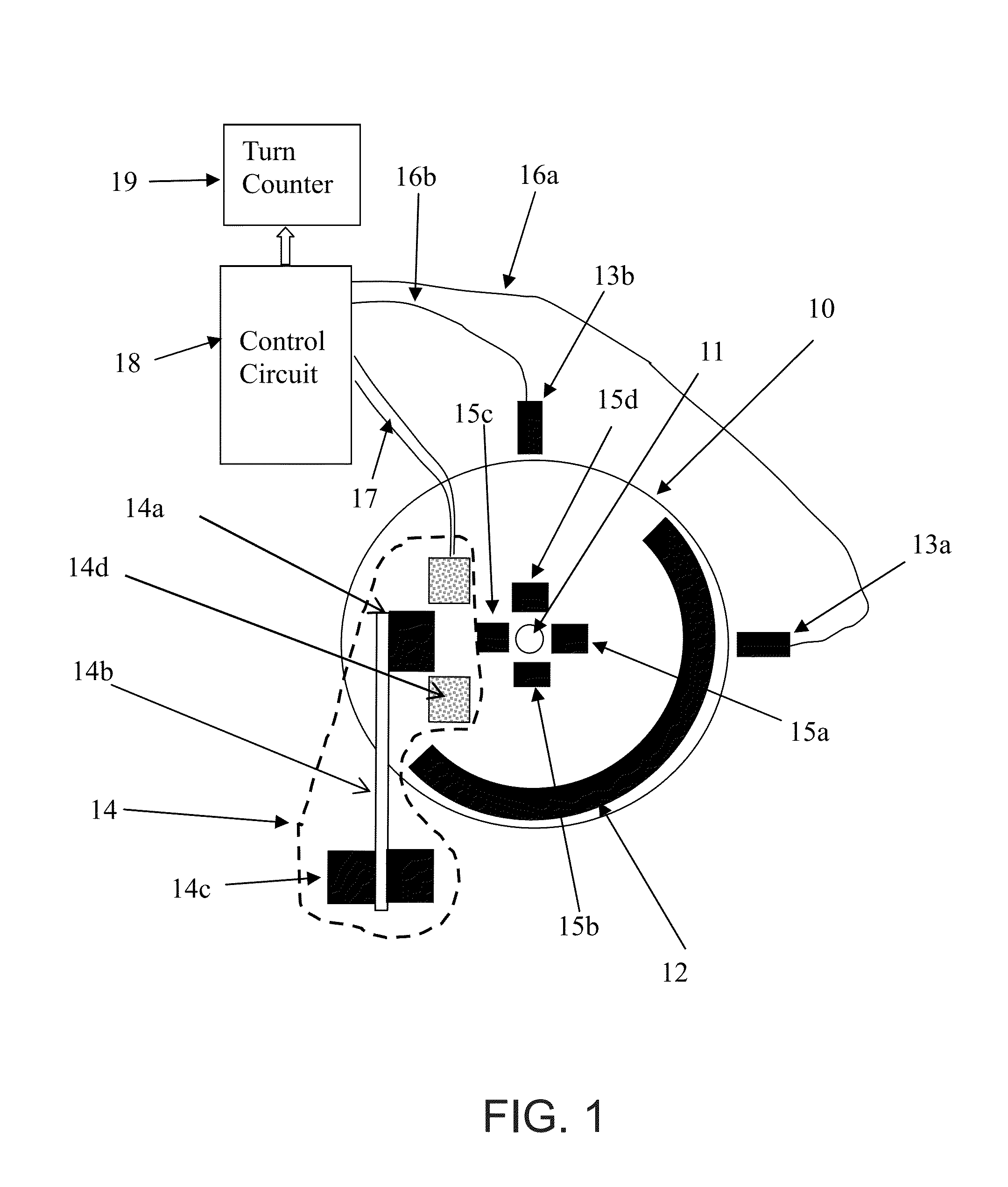
[0032]Reference is first made to FIG. 1 schematically illustrating one form of measuring apparatus constructed in accordance with the present invention for measuring the turns or rotations of a shaft 10 about a rotary axis 11. The apparatus illustrated in FIG. 1 may be in the form of a stand-alone turns counter, or a one-turn absolute encoder providing a precise measurement of the rotation angle of the shaft. As will be shown below, the apparatus illustrated in FIG. 1 is designed for recording the number of turns and / or fractions of a turn, without the need for external power, since the required power is received from the rotating shaft by means of magnetic induction.

[0033]Thus, as shown in FIG. 1, the rotary shaft 10 itself, whose rotations are to be counted, or a separate disc fixed to that shaft, includes a first machine-sensible element 12 extending around the outer circumference of the shaft for a length defining one-half of a period of displacement (one rotation) of the shaft....


PUM


Abstract

Apparatus and method for measuring displacements of a rotary or linearly-displaceable member by counting periods of displacement thereof along a predetermined displacement path, including a pulse generator located at a pulse-generation station proximate to the displacement path; and an electrical circuit controlled by the pulse generator to actuate a first sensor to sense the status of the displaceable member at the particular instant one of said second machine-sensible elements passes through the pulse-generation station, and to increment a counter in accordance with said status determination. In the described preferred embodiments, the second machine-sensible elements are magnetic elements; and the pulse generator includes a coil, a magnetic core magnetically coupled to the coil, and a spring-mounting for the magnetic core causing the core to move from an initial position in one direction with respect to the coil when aligned with one of the second machine-sensible elements, and to be returned in the opposite direction by the spring to its initial position, whereby the coil generates pulses during such movements of the magnetic core.

Description

RELATED APPLICATIONS[0001]This Application is a National Phase of PCT Patent Application No. PCT / IL2008 / 001190 having International filing date of Sep. 3, 2008, which claims the benefit of U.S. Provisional Patent Application No. 60 / 935,857 filed on Sep. 4, 2007. The contents of the above Applications are all incorporated herein by reference.FIELD AND BACKGROUND OF THE INVENTION[0002]The present invention relates to apparatus and methods for measuring displacements of a displaceable member along a predetermined displacement path. The invention is described below particularly with respect to rotary displaceable members such as in rotary encoders, but may also be used with respect to linearly-displaceable members, such as in linear encoders.[0003]The displacement of rotary members is usually measured by counting the number of turns or revolutions experienced by the rotary member as well as fractions thereof, which fractions determine the resolution of the measurement apparatus. Turn co...

Claims


Application Information

Patent Timeline
Patent Type & Authority Patents(United States)
IPC IPC(8): G01B7/30
CPCG01D5/244
Inventor VILLARET, YVES
Owner YASKAWA EURO TECH
Why Eureka
Try Eureka