Laser ultrasonic nondestructive testing equipment and method adopting light deflection method

A laser ultrasonic and non-destructive testing technology, applied in measuring devices, material analysis by optical means, instruments, etc., can solve the problems affecting the signal strength of laser ultrasonic flaw detection, signal synchronization delay, complex structure, etc., to achieve easy debugging equipment, The effect of portable equipment and simple structure

Active Publication Date: 2022-02-08
宝宇(武汉)激光技术有限公司
View PDF6 Cites 0 Cited by
  • Summary
  • Abstract
  • Description
  • Claims
  • Application Information

AI Technical Summary

Problems solved by technology

The mainstream laser ultrasonic equipment currently in use consists of two parts: laser excitation and laser interference receiving. The equipment is large in size and complex in structure. There are delay problems in the synchronization between signals and interference problems between devices, which affect the signal strength of laser ultrasonic flaw detection.

Method used


Image

  • Laser ultrasonic nondestructive testing equipment and method adopting light deflection method

Examples


Embodiment 1

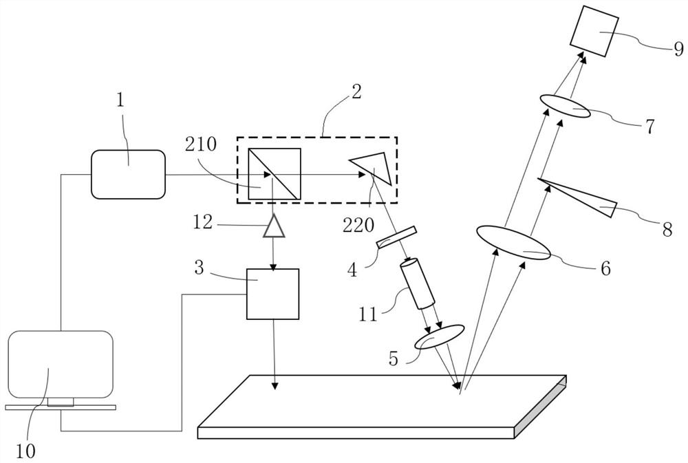
[0043] Such as figure 1 As shown, a laser ultrasonic non-destructive testing equipment by optical deflection method, including:

[0044] Laser 1, beam splitting device 2, vibrating mirror 3, energy attenuation device 4, first positive lens 5, second positive lens 6, third positive lens 7, shading device 8, photodiode 9 and signal processing terminal 10;

[0045] The laser 1 is used to emit pulsed laser;

[0046] The beam splitting device 2 is arranged at the exit end of the laser 1. The beam splitting device 2 has two exit ends. The pulsed laser light emitted by the laser 1 enters the beam splitting device 2 and is divided into two beams by the beam splitting device 2. shoot out from one exit end;

[0047] The vibrating mirror 3 is arranged at one of the exit ends of the beam splitting device 2, and the pulse laser emitted from one of the exit ends of the beam splitting device 2 will enter the vibrating mirror 3, and then the vibrating mirror 3 converts the incoming point la...

Embodiment 2

[0058] Such as figure 1 As shown, the present embodiment is a further optimization carried out on the basis of embodiment 1, which is specifically as follows:

[0059] The optical deflection method laser ultrasonic nondestructive testing equipment also includes an optical switch 12,

[0060] The optical switch 12 is arranged between the output end of the beam splitting device 2 and the input end of the vibrating mirror 3. The optical switch 12 is used to realize the on-off of the light, so as to control the light output at point intervals. The sensitivity of the optical switch 12 should reach more than 1ms .

Embodiment 3

[0062] Such as figure 1 As shown, the present embodiment is a further optimization carried out on the basis of embodiment 1 or 2, which is specifically as follows:

[0063] The beam splitting device 2 includes: a beam splitting prism 210 and a mirror 220;

[0064] The beam splitting prism 210 is arranged at the output end of the laser 1, and the beam splitting prism 210 has two output ends;

[0065] The pulsed laser light emitted by the laser 1 enters the beam-splitting prism 210, and is divided into two beams by the beam-splitting prism 210, and then emitted from the two output ends respectively;

[0066] Reflector 220, which is arranged at one of the exit ends of beam splitting prism 210;

[0067] The oscillating mirror 3 and the energy attenuating device 4 are respectively arranged at the other output end of the beam splitting prism 210 and the reflection end of the mirror 220 .

[0068] The pulse laser emitted from one of the output ends of the beam-splitting prism 210 ch...


PUM


Abstract

The invention relates to laser ultrasonic nondestructive testing equipment adopting a light deflection method, which is characterized in that a beam splitter is arranged at the emergent ends of a laser and is provided with two emergent ends; a galvanometer is arranged at one emergent end of the beam splitting device; an energy attenuation device is arranged at the other emergent end of the beam splitting device; a first positive lens is arranged at the emergent end of the energy attenuation device; a second positive lens and the first positive lens are arranged on the same side; a third positive lens is arranged at the emergent end of the second positive lens; a shading device is arranged between the second positive lens and the third positive lens and is used for partially shading a light beam emitted from the second positive lens to the third positive lens; a photodiode is arranged at the emergent end of the third positive lens; and a signal processing end is electrically connected with the laser, the galvanometer and the photodiode respectively. The equipment has the advantages that ultrasonic signals are detected through the optical non-interference technology, equipment is easier to debug, laser ultrasonic signal excitation and ultrasonic signal receiving can be completed only through one laser, cost is extremely low, and laser excitation and laser receiving are synchronous in real time.

Description

technical field [0001] The invention relates to the technical field of laser non-destructive testing, in particular to a laser ultrasonic non-destructive testing device and method using an optical deflection method. Background technique [0002] Laser ultrasound is a non-contact, high-precision, non-destructive new ultrasonic testing technology. It uses laser pulses to excite ultrasonic waves in the workpiece to be detected, and uses signal detection equipment to detect the propagation of ultrasonic waves, thereby obtaining workpiece information, such as workpiece thickness, internal And surface defects, material parameters and so on. The mainstream laser ultrasonic equipment currently used includes two parts: laser excitation and laser interference receiving. The equipment is large in size and complex in structure. There is a delay problem in the synchronization between signals and there is interference between the devices, which affects the signal strength of laser ultraso...

Claims


Application Information

Patent Timeline
Patent Type & Authority Applications(China)
IPC IPC(8): G01N21/17G01N21/01
CPCG01N21/1702G01N21/01
Inventor 李震刘鉴霆周永祥王亦军
Owner 宝宇(武汉)激光技术有限公司
Why Eureka
Try Eureka