Variable valve lift apparatus

a technology of variable valves and lift apparatuses, which is applied in the direction of valve details, valve arrangements, machines/engines, etc., can solve the problems of difficulty in actual manufacture of apparatuses, and achieve the effect of reducing the moment of inertia and obtaining dynamic characteristics

Active Publication Date: 2013-06-18
HYUNDAI MOTOR CO LTD
View PDF8 Cites 30 Cited by
  • Summary
  • Abstract
  • Description
  • Claims
  • Application Information

AI Technical Summary

Benefits of technology

[0011]Various aspects of the present invention provide for a variable valve lift apparatus having the advantage of obtaining dynamic characteristics by reducing the moment of inertia of the variable valve lift apparatus, in which a latching portion is inserted into an inner body and positioned midway between a valve member and a hinge member, and a lost motion hinge point and the hinge member are positioned in the same direction relative to a camshaft.
[0020]According to the above-described variable valve lift apparatus, dynamic characteristics can be obtained by reducing the moment of inertia of the variable valve lift apparatus, and the dynamic characteristics can be further improved by inserting the latching portion into the inner body so as to be closer to the camshaft.

Problems solved by technology

Also, a valve member is positioned under the lost motion spring 50, and such an apparatus has to press the valve member, thereby making the actual manufacture of the apparatus difficult.

Method used


Image

  • Variable valve lift apparatus
  • Variable valve lift apparatus
  • Variable valve lift apparatus

Examples


Embodiment Construction

[0035]Reference will now be made in detail to various embodiments of the present invention(s), examples of which are illustrated in the accompanying drawings and described below. While the invention(s) will be described in conjunction with exemplary embodiments, it will be understood that present description is not intended to limit the invention(s) to those exemplary embodiments. On the contrary, the invention(s) is / are intended to cover not only the exemplary embodiments, but also various alternatives, modifications, equivalents and other embodiments, which may be included within the spirit and scope of the invention as defined by the appended claims.

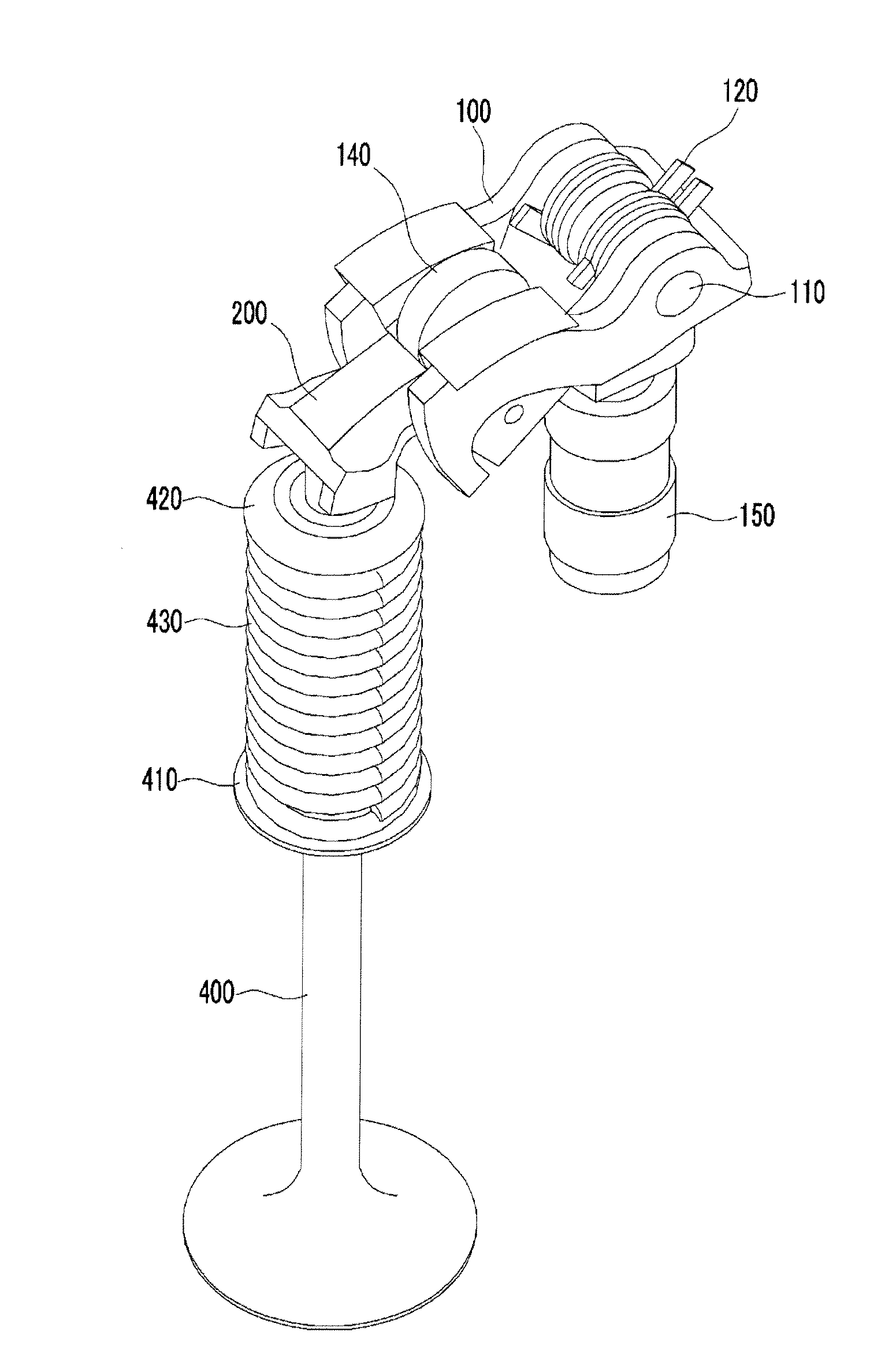
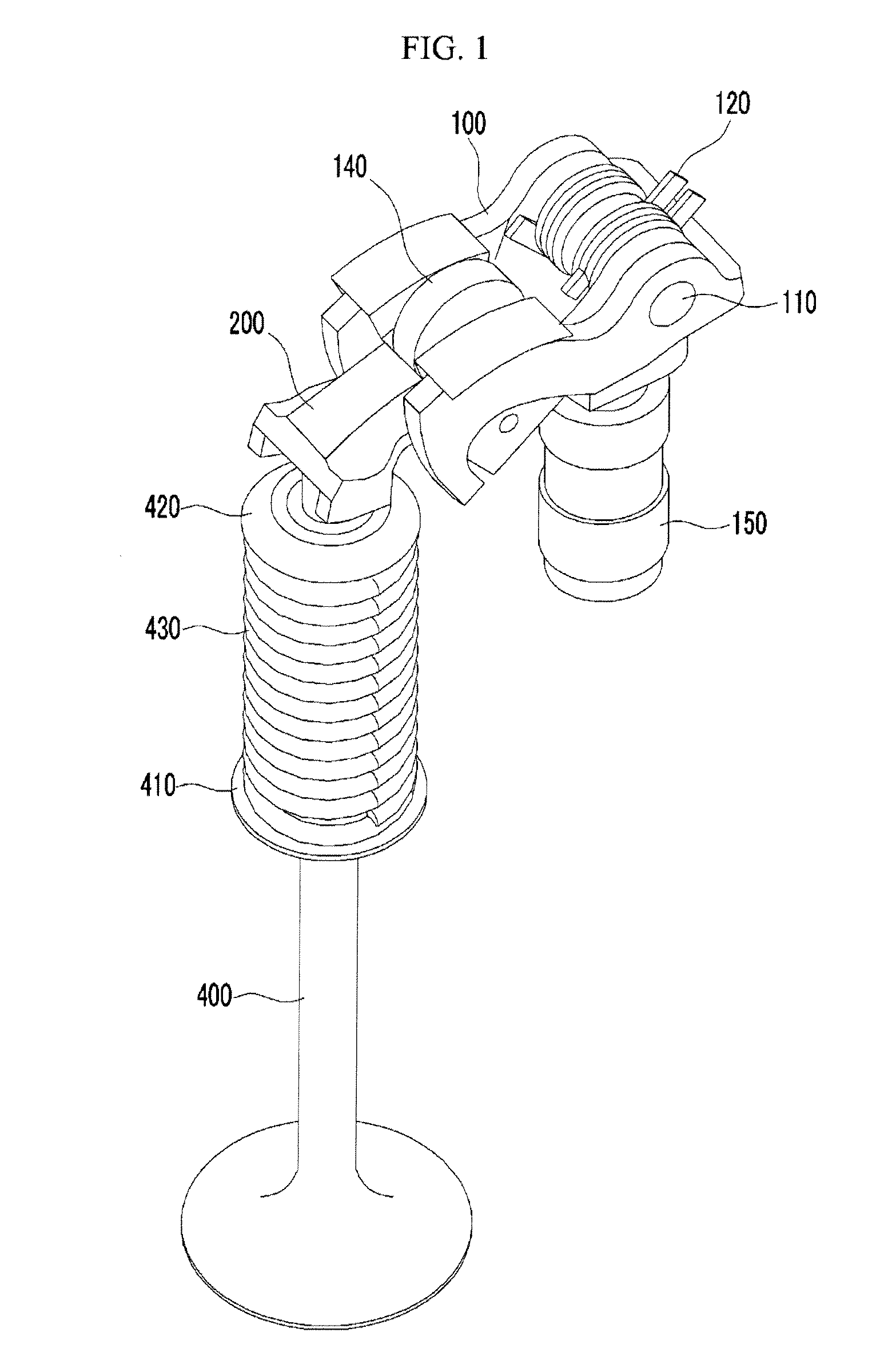
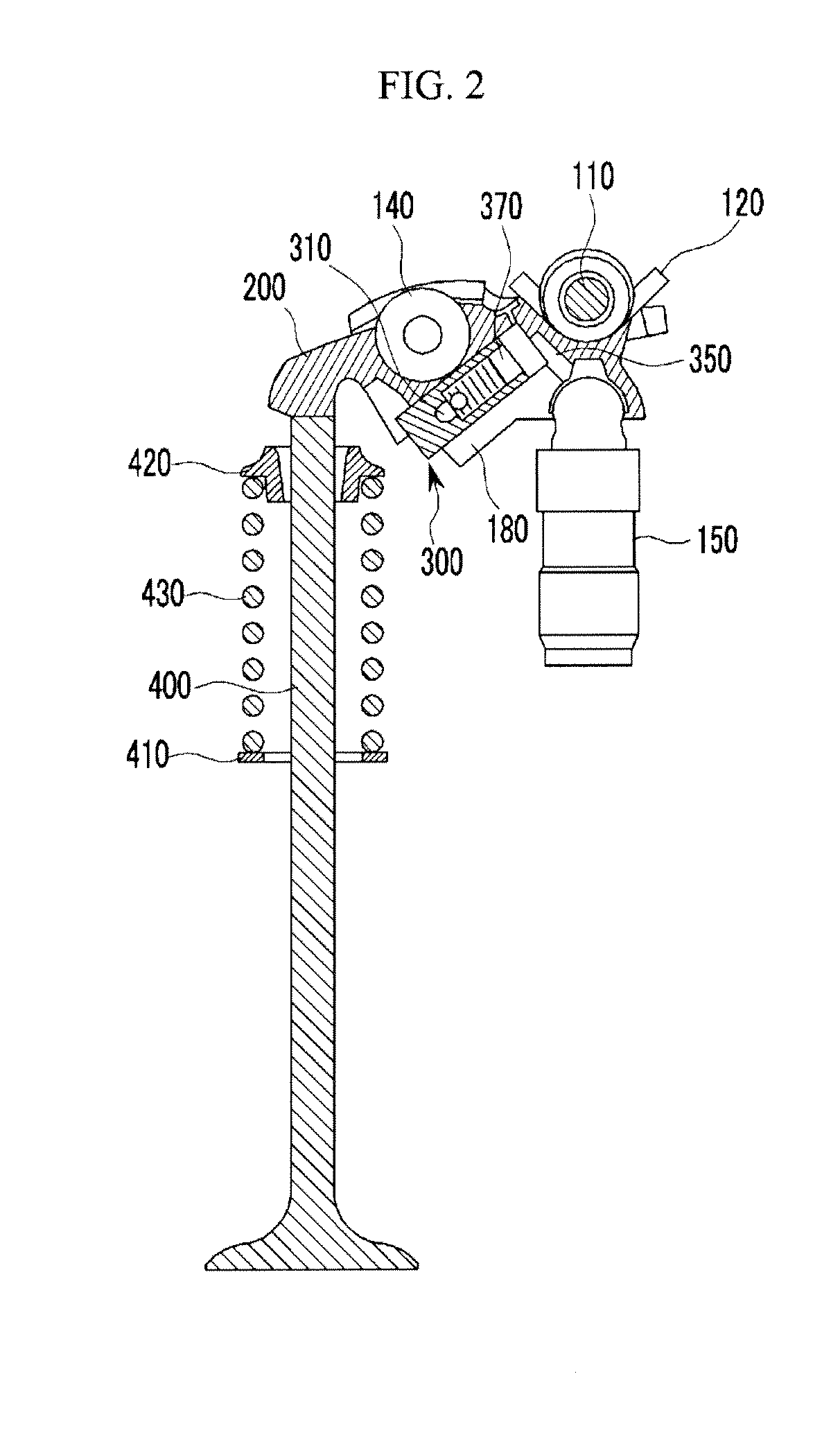
[0036]In the variable valve lift apparatus of the present invention, rotating high and low cams having different cam profiles and arranged side by side on an outer side of a cylinder are respectively in rolling contact with the outer body or the inner body, and the outer body and the inner body are connected coaxially with the lost mo...


PUM


Abstract

A variable valve lift apparatus includes a high cam and a low cam fixed side by side to a camshaft, an outer body pressed by the rotation of the high cam, and has a crossbar formed at the bottom of the front end, an inner body, of which the front end protrudes further than the outer body, the lower front end is provided with a valve member, the upper rear end is hinged to a lost motion hinge shaft coaxially with the rear end of the outer body, and the lower rear end is pivotally connected to a hinge member, and a latching portion inserted into the inner body and selectively connected to the crossbar of the outer body to move the inner body dependent on movement of the front end of the outer body, wherein the lost motion hinge shaft is disposed in the same direction as a hinge point between the inner body and the hinge member with respect to the camshaft. Dynamic characteristics can be obtained by reducing the moment of inertia of the variable valve lift apparatus, and the dynamic characteristics can be further improved by inserting the latching portion into the inner body so as to be closer to the camshaft.

Description

CROSS-REFERENCE TO RELATED APPLICATION[0001]This application claims priority to and the benefit of Korean Patent Application No. 10-2010-0103359 filed Oct. 22, 2010, the entire contents of which application is incorporated herein for all purposes by this reference.BACKGROUND OF INVENTION[0002]1. Field of Invention[0003]The present invention relates to a variable valve lift apparatus, and more particularly, to a variable valve lift apparatus in which a latching portion connecting an inner body and an outer body is disposed adjacent to a cam, and a lost motion hinge shaft and a hinge point of the variable valve lift apparatus are disposed in the same direction relative to a camshaft.[0004]2. Description of Related Art[0005]In general, an internal combustion engine generates power by taking in fuel and air and burning it in a combustion chamber. Intake valves are operated by a camshaft in order to intake the air, and the air is drawn into the combustion chamber while the intake valves ...

Claims


Application Information

Patent Timeline
Patent Type & Authority Patents(United States)
IPC IPC(8): F01L1/18
CPCF01L1/185F01L13/0036F01L1/2405F01L2105/00F01L2820/033F01L2001/186F01L2305/00
Inventor CHOI, BYONG YOUNGKWAK, YOUNG HONGSHIN, GEE-WOOKWOO, YOONSIKKONG, JIN KOOKWOO, SOO-HYUNG
Owner HYUNDAI MOTOR CO LTD
Why Eureka
Try Eureka