Vehicle

a technology of exhaust pipe and vehicle, which is applied in the field of vehicles, can solve the problem of high placement of fuel tanks

Inactive Publication Date: 2011-11-22
YAMAHA MOTOR CO LTD
View PDF14 Cites 5 Cited by
  • Summary
  • Abstract
  • Description
  • Claims
  • Application Information

AI Technical Summary

Benefits of technology

[0012]In this embodiment, a rear arm may be supported swingably by a body frame, and the exhaust pipe disposed apart from the rear arm by a given distance, when viewed from the side of the vehicle. Such a construction eliminates the need for a clearance designed to prevent the exhaust pipe from contacting the rear arm, and therefore, eliminates the need for the rear arm to have a thinner part. This ensures rigidity of the rear arm.
[0013]In another embodiment, the winding-form part is located at the rear of a fuel tank. The fuel tank is thereby not located above both the rear suspension and the winding-form part, and is thus not too high. A center of gravity of the fuel tank is therefore close to a center of gravity of the vehicle, when the center of gravity of the vehicle is located lower than the center of gravity of the fuel tank, thereby reducing the moment of inertia about the center of gravity of the vehicle. This improves operability of the vehicle about its center of gravity.
[0016]In another embodiment, a silencer is connected to the exhaust pipe and located at the upper side and the rear of the engine. A chain is located on the side opposed to the silencer in a vehicle width direction to drive the rear wheel. The winding-form part includes a portion located on the silencer side in the vehicle width direction; a portion connected to the portion located on the silencer side and extending toward the chain side in the vehicle width direction; and a portion connected to the portion extending toward the chain side, while being connected to the silencer. Such a construction allows the winding-form part to extend from the silencer side toward the chain side, and back to the silencer side. Thereby, a space defined between the silencer and the chain is more effectively utilized as a region where the winding-form part is disposed.
[0018]In another embodiment, a part of the exhaust pipe adjacent to a connecting part connected to the engine is substantially in a straight form. Exhaust resistance of air discharged from the engine is thereby reduced, and engine performance is improved.
[0019]In another embodiment, a silencer is connected to the exhaust pipe and located at the upper side and the rear of the engine. An axis of connection between the exhaust pipe and the silencer is higher than an axis of connection between the exhaust pipe and the engine. Such a construction allows the exhaust pipe to connect to the silencer without passing below the engine. Therefore, the exhaust pipe is not damaged by contact with the ground during off-road travel, such as on mountain roads.

Problems solved by technology

This, however, leads to a problem that the location of the fuel tank is too high.

Method used


Image

  • Vehicle
  • Vehicle
  • Vehicle

Examples


Embodiment Construction

[0029]An embodiment of the present invention is now described with reference to the drawings.

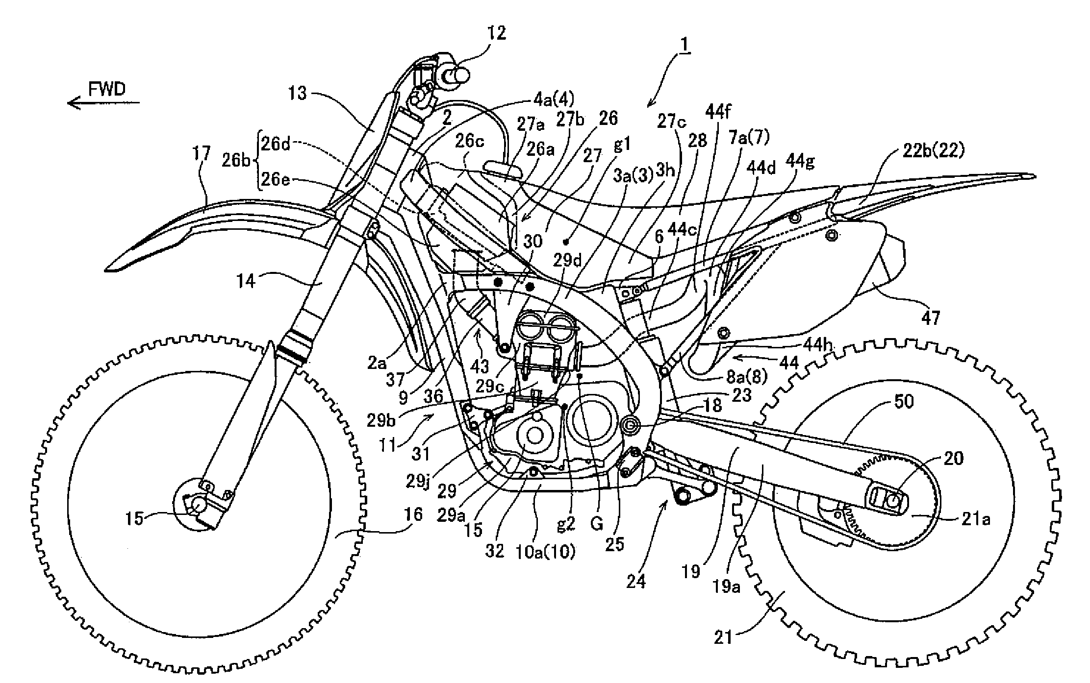
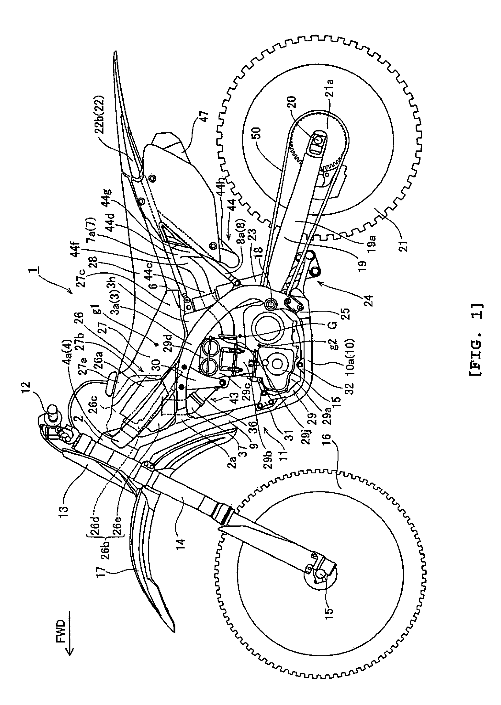
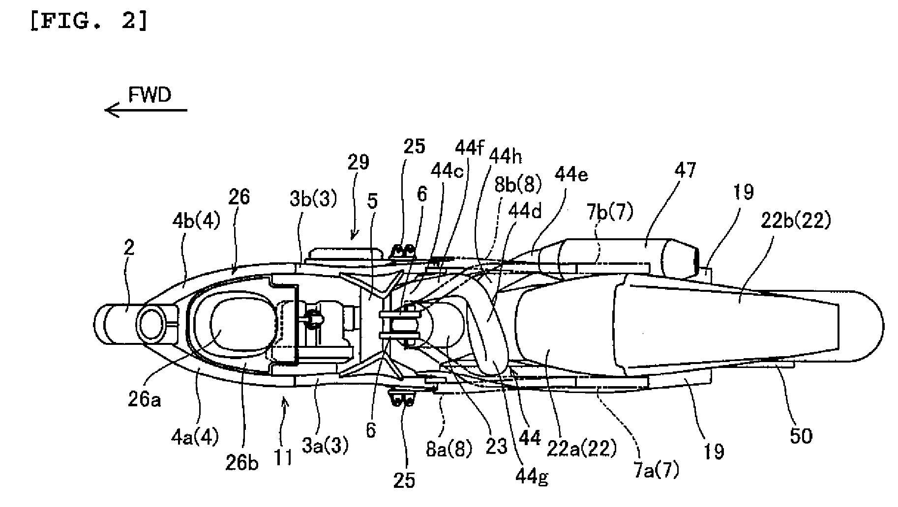
[0030]FIG. 1 is a side view of a motorcycle 1 according to one embodiment of the present invention. FIGS. 2-7 illustrate a structure of motorcycle 1 according to the embodiment shown in FIG. 1. An off-road motorcycle is described as an example embodiment of the invention. The direction indicated by arrow FWD in the drawings is a forward traveling direction of the motorcycle.

[0031]In motorcycle 1, with reference to FIGS. 1 and 2, a left frame 3a and a right frame 3b of a main frame 3 are connected to a connecting part 2a of a head pipe 2. Left and right in this description are the left and right sides as viewed from a rider facing the forward traveling direction (the direction indicated by arrow FWD). Left frame 3a and right frame 3b extend downward to the rear. A left tank rail 4a and a right tank rail 4b of a tank rail 4 are located between a rear part of head pipe 2 and top parts of left f...


PUM


Abstract

A vehicle having a sufficient length of exhaust pipe and a member disposed above a rear suspension that is not too high. An exhaust pipe is connected to a rearward side of an engine. A rear suspension absorbs shocks generated when a rear wheel moves up and down. A coil-form part of the exhaust pipe is located between the rear suspension and a tire house of the rear wheel, within which the rear wheel moves up and down.

Description

RELATED APPLICATIONS[0001]This application claims the benefit of priority under 35 USC 119 of Japanese patent application no. 2006-308757, filed on Nov. 15, 2006, Japanese patent application no. 2007-022581, filed on Feb. 1, 2007, and Japanese patent application no. 2007-272716, filed on Oct. 19, 2007, which applications are hereby incorporated by reference in their entireties.BACKGROUND OF THE INVENTION[0002]1. Field of the Invention[0003]The present invention relates to a vehicle, and more particularly relates to a vehicle having an exhaust pipe.[0004]2. Description of Related Art[0005]Conventionally, a vehicle having an exhaust pile has been known. JP-Y-Hei 4-18898, for example, discloses a motorcycle having an exhaust pipe connected to a rearward side of an engine; a shock absorber (rear suspension) located below the exhaust pipe to absorb shocks generated when a rear wheel moves up and down; and a fuel tank located above the shock absorber and the exhaust pipe. In order to ensu...

Claims


Application Information

Patent Timeline
Patent Type & Authority Patents(United States)
IPC IPC(8): B60K13/04F01N13/08
CPCB62K11/04
Inventor MIYASHIRO, SHIDEHIKOOGURI, KIYOHIKOOKAMOTO, TOSHIO
Owner YAMAHA MOTOR CO LTD
Why Eureka
Try Eureka