

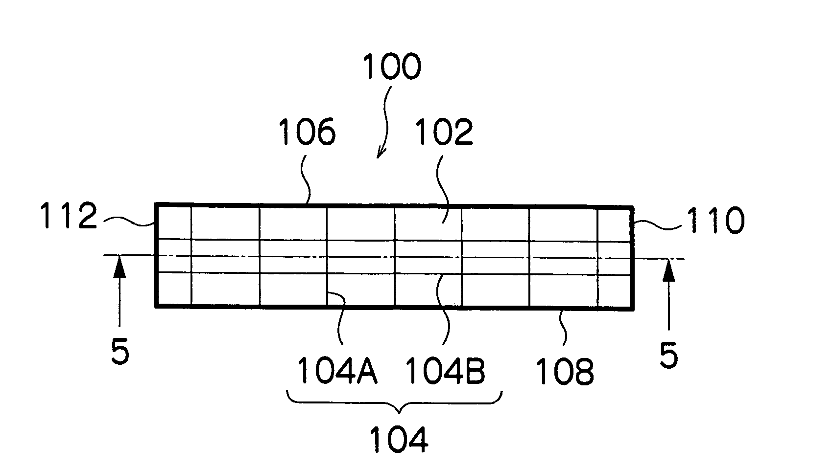
Laminated structure formed of thin plates
a technology of laminate structure and thin plate, which is applied in the direction of thin material processing, printing, layered products, etc., can solve the problems of thin plate member warping, etc., and achieve the effect of increasing the volume (cross-sectional surface area) of the groove, ensuring the rigidity of the thin plate member, and increasing the amount of adhesiv
- Summary
- Abstract
- Description
- Claims
- Application Information
AI Technical Summary
Benefits of technology
Problems solved by technology
Method used
Image


Examples
Embodiment Construction
[0055]Below, a preferred embodiment of the present invention is described with reference to the accompanying drawings.
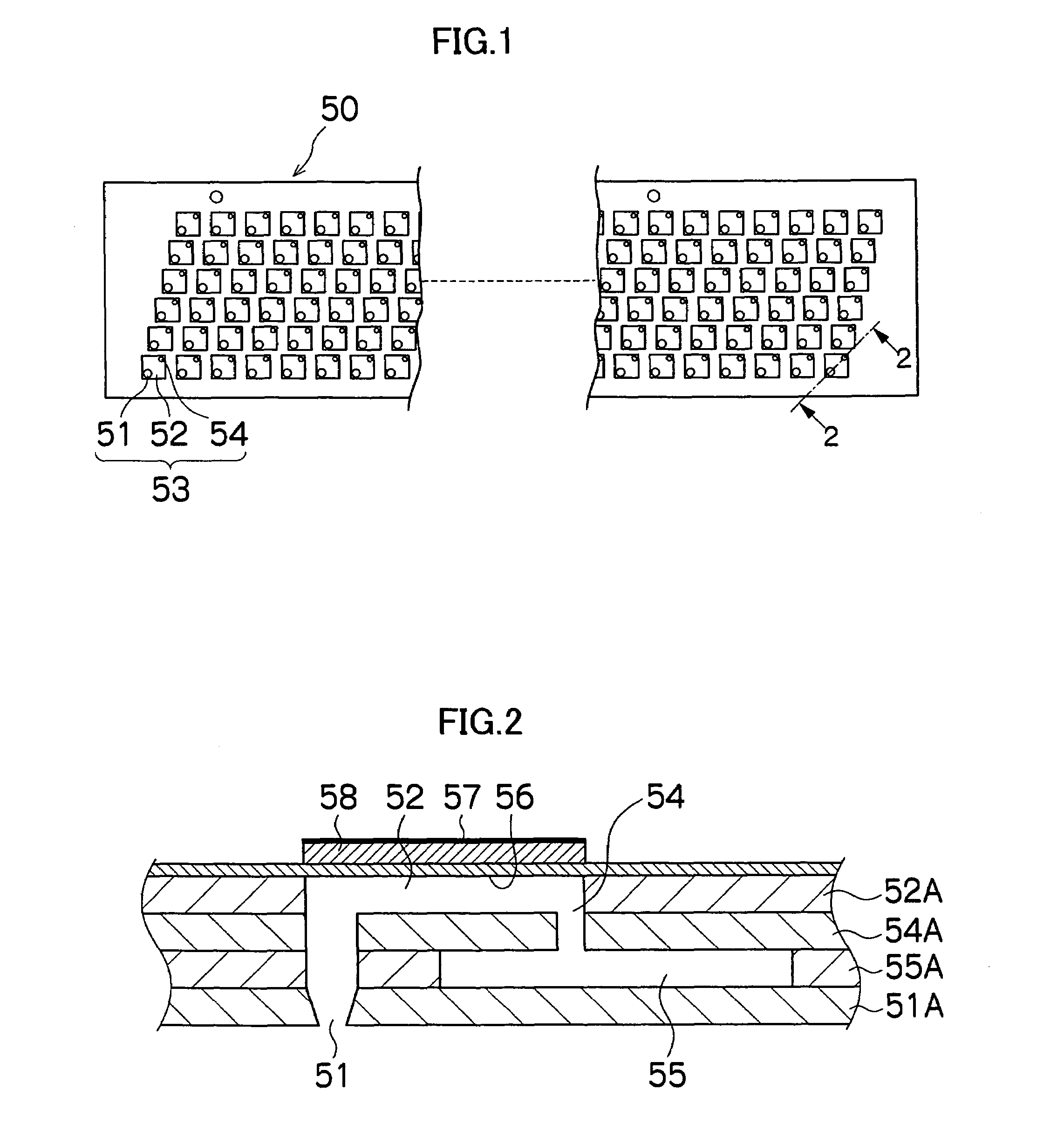
[0056]FIG. 1 is a plan view perspective diagram showing an example of the structure of an inkjet recording head (print head) 50 to which an embodiment of the present invention is applied. FIG. 2 is a cross-sectional diagram (along line 2-2 in FIG. 1) showing the three-dimensional structure of an ink chamber unit of the print head 50.
[0057]The print head 50 is a line type head, which has the length in the lateral direction in FIG. 1 corresponding to the maximum paper width and considerably longer than the breadth in the vertical direction in FIG. 1. In order to increase the density of the nozzles by reducing the nozzle pitch, the print head 50 in the present example has a structure wherein a plurality of ink chamber units 53, each comprising a nozzle 51 for discharging ink droplets, a pressure chamber 52 corresponding to the nozzle, and the like, are disposed in a sta...
PUM
| Property | Measurement | Unit |
|---|---|---|
| aspect ratio | aaaaa | aaaaa |
| aspect ratio | aaaaa | aaaaa |
| aspect ratio | aaaaa | aaaaa |
Abstract
Description
Claims
Application Information