Cab structure for construction machine

a construction machine and cab technology, applied in soil shifting machines/dredgers, roofs, transportation and packaging, etc., can solve the problems of achieve the effect of ensuring the rigidity of the cab structure and reducing the rigidity of the cab

Inactive Publication Date: 2009-05-21
KOMATSU LTD
View PDF10 Cites 20 Cited by
  • Summary
  • Abstract
  • Description
  • Claims
  • Application Information

AI Technical Summary

Benefits of technology

[0008]It is an object of the present invention is to provide a cab structure for a construction machine that includes a plurality of pole members and can ensure the rigidity of the cab structure.
[0046]In this cab structure for a construction machine, the electrical equipment is accommodated in the inside accommodation space. Therefore, it is possible to protect the electrical equipment from wind and weather.

Problems solved by technology

However, the aforementioned known cab structure for construction machine has the following problems.
But, in the cab structure that includes the pole member shorter than other pole members, in the case where all the mount portions are arranged at the same level, the rigidity of the cab will largely decrease.

Method used


Image

  • Cab structure for construction machine
  • Cab structure for construction machine
  • Cab structure for construction machine

Examples


first embodiment

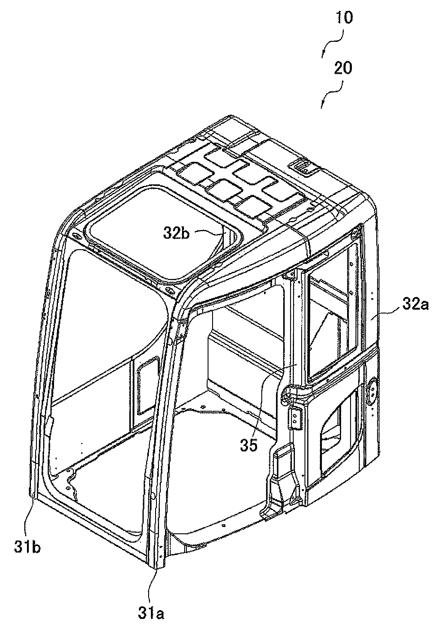
[0065]With reference to FIGS. 1 through 13, the following description will describe a hydraulic excavator (construction machine) 1 that includes an operator compartment (cab) to which a cab structure for a construction machine according to one embodiment of the present invention is adopted.

[0066]As used herein to describe the present invention, terms “left and right”, “front and rear”, and “front portion and rear side” should be interpreted as directions relative to an operator when sitting on a seat in a cab 10 (see FIG. 1, for example).

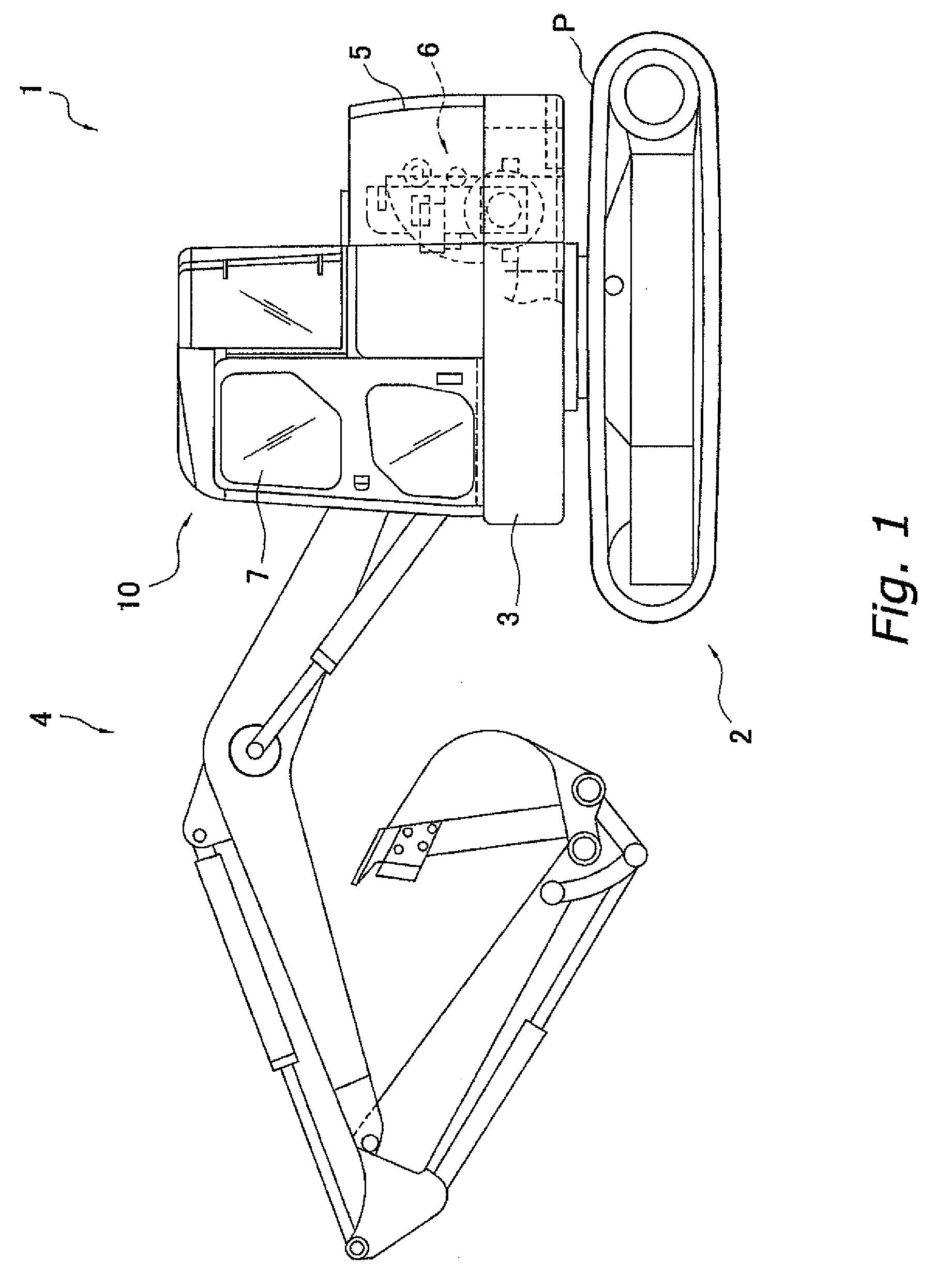
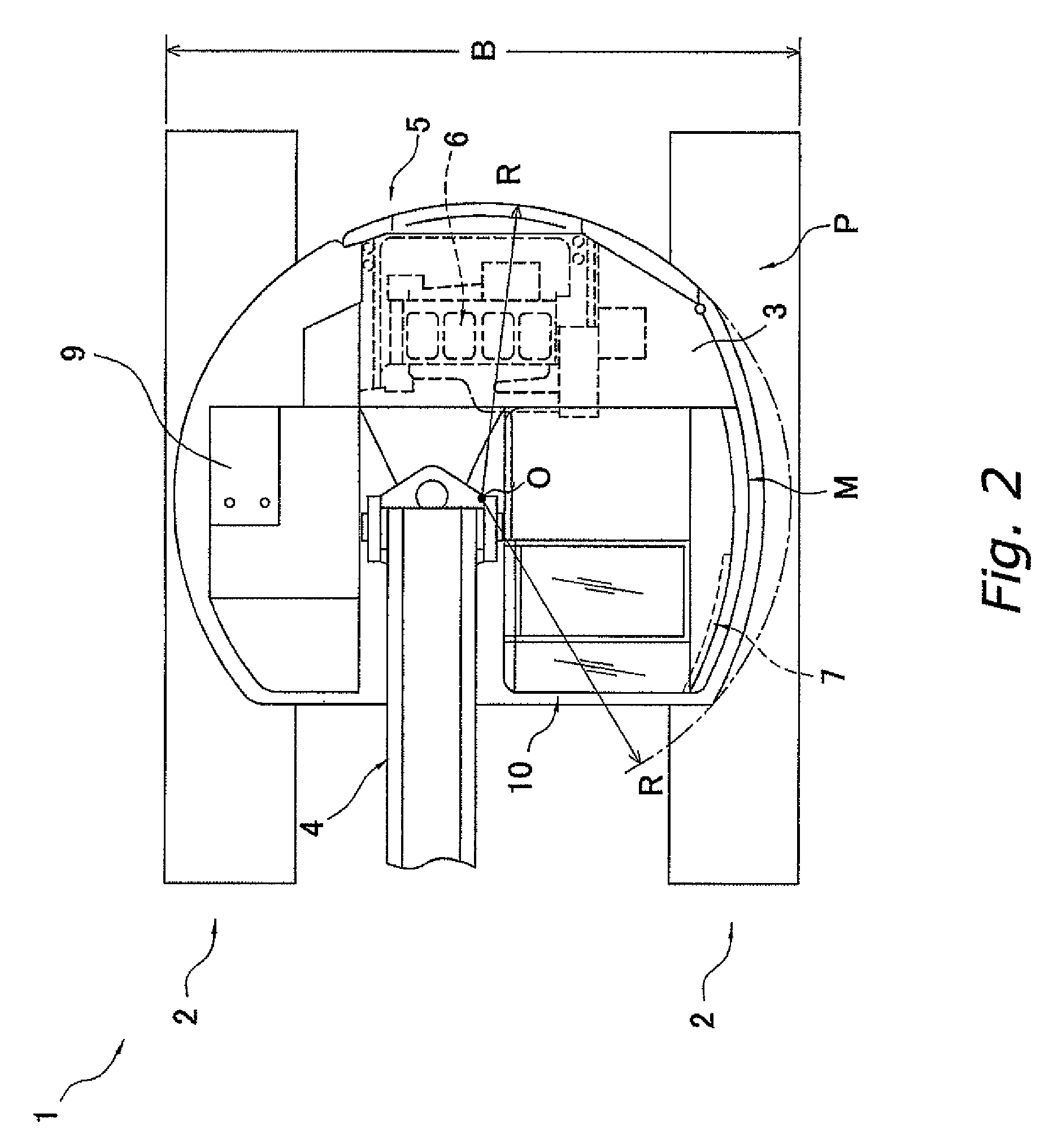
Entire Configuration of Hydraulic Excavator 1

[0067]The hydraulic excavator 1 according to this embodiment includes a lower traveling unit 2, a revolving base (upper revolving unit) 3, a working machine 4, a counterweight 5, an engine 6, an equipment compartment 9, and the cab 10, as shown in FIGS. 1 and 2. The hydraulic excavator 1 is a small rear-swing radius type hydraulic excavator that has the revolving radius R of the machine except the working...

second embodiment

[0107]With reference to FIGS. 1, 2, 5 and 14 through 18, the following description will describe a hydraulic excavator (construction machine) 1 that includes an operator compartment (cab) to which a cab structure for a construction machine according to another embodiment of the present invention is adopted.

[0108]Note that components that have the same functions as the components described in the foregoing first embodiment are attached with the same reference numerals and their description is omitted. In addition to this, directions in this embodiment should be also interpreted similarly to those in the foregoing first embodiment.

[0109]As shown in FIG. 5, the cab 10 according to this embodiment is installed on four mount portions 24 that are formed in the front-left side of the turning frame 25 as the upper portion of the turning base 3 with vibration isolators 24a and a floor panel 27 being fastened on a floor frame 27a of the cab 10 by bolts (not shown). Thus, the cab 10 is fixedly...


PUM


Abstract

A cab structure for a construction machine that includes a plurality of pole members and can ensure the rigidity of the cab structure for a construction machine is provided. The cab structure unit includes the rear-right pole member that has a length that is shorter than other pole member (rear-left pole member) and does not reach the level of a floor panel (joint panel) so that the recessed space is formed in the rear side of the cab (10). The rear-right pole member is joined to the first rear panel portion and the plate-shaped member as a reinforcement member that reinforces a part from the lower end of the rear-right pole member to the height position of the floor panel.

Description

CROSS-REFERENCE TO RELATED APPLICATIONS[0001]This U.S. National stage application claims priority under 35 U.S.C. § 119(a) to Japanese Patent Application No. 2005-208252, filed in Japan on Jul. 19, 2005, and Japanese Patent Application No. 2005-208253, filed in Japan on Sep. 6, 2005. The entire contents of Japanese Patent Application Nos. 2005-208252 and 2005-258523 are hereby incorporated herein by reference.TECHNICAL FIELD[0002]The present invention relates to, in a construction machine that includes an upper revolving unit on a lower traveling unit, an operator compartment (cab) structure that is mounted on the upper revolving unit.BACKGROUND ART[0003]In the field of civil engineering works that excavates earth, stone and so on, construction machines such as a hydraulic excavator (excavator) have been used in works.[0004]This type of hydraulic excavator mainly includes a lower traveling unit, an upper revolving unit that is revolvably mounted to the lower traveling unit, and an o...

Claims


Application Information

Patent Timeline
Patent Type & Authority Applications(United States)
IPC IPC(8): B62D33/06
CPCB62D33/0617E02F9/163B62D33/0633B62D25/04B62D25/08E02F9/16B62D25/06
Inventor TSUKAMOTO, DAISUKETSUJI, KOUDOU
Owner KOMATSU LTD
Why Eureka
Try Eureka