Press-formed member having corner portion, press-formed member manufacturing apparatus and press-formed member manufacturing method

a technology of press-formed members and manufacturing methods, which is applied in the direction of manufacturing tools, forging/hammering/pressing machines, manufacturing methods, etc., can solve the problems of increased production costs, increased production costs, and increased production costs, and achieves the reduction of the thickness of the bent portion (corner portion) of the conventional press-formed member, excellent productivity, and increased weight of the press-formed member

Inactive Publication Date: 2007-06-07
NISSAN MOTOR CO LTD
View PDF5 Cites 21 Cited by
  • Summary
  • Abstract
  • Description
  • Claims
  • Application Information

AI Technical Summary

Benefits of technology

[0008] Although the press forming method provides excellent productivity, the thickness of the bent portion (corner portion) of the conventional press-formed member is reduced during the press forming process. Therefore, it is necessary to use a thick plate blank member as the material of the press-formed member to ensure the rigidity of the press-formed member taking into account that the thickness of the corner portion is reduced during the press forming process. Therefore, in the conventional press-formed member manufacturing method the weight of the press-formed member is increased and the material cost (manufacturing cost) is increased.

Problems solved by technology

Therefore, in the conventional press-formed member manufacturing method the weight of the press-formed member is increased and the material cost (manufacturing cost) is increased.
However, the welding process is time-consuming, and thus, the productivity drops and the manufacturing cost increases.

Method used


Image

  • Press-formed member having corner portion, press-formed member manufacturing apparatus and press-formed member manufacturing method
  • Press-formed member having corner portion, press-formed member manufacturing apparatus and press-formed member manufacturing method
  • Press-formed member having corner portion, press-formed member manufacturing apparatus and press-formed member manufacturing method

Examples


second embodiment

[0101] Referring now to FIGS. 16 to 19, a press-formed member manufacturing apparatus in accordance with a second embodiment will now be explained. In view of the similarity between the first and second embodiments, the parts of the second embodiment that are identical to the parts of the first embodiment will be given the same reference numerals as the parts of the first embodiment. Moreover, the descriptions of the parts of the second embodiment that are identical to the parts of the first embodiment may be omitted for the sake of brevity.

[0102]FIG. 16 is a partial cross sectional view of a thickness increasing device 250 of a press-formed member manufacturing apparatus in accordance with a second embodiment of the present invention. FIG. 17 is a partial cross sectional view of the thickness increasing device 250 of the press-formed member manufacturing apparatus illustrating a pressure-forming process for increasing the thickness of the corner portion of a press-formed member. F...

third embodiment

[0108] Referring now to FIGS. 20 and 21, a press-formed member manufacturing apparatus in accordance with a third embodiment will now be explained. In view of the similarity between the first and third embodiments, the parts of the third embodiment that are identical to the parts of the first embodiment will be given the same reference numerals as the parts of the first embodiment. Moreover, the descriptions of the parts of the third embodiment that are identical to the parts of the first embodiment may be omitted for the sake of brevity.

[0109]FIG. 20 is a partial cross sectional view of a thickness increasing device 350 of the press-formed member manufacturing apparatus in accordance with the third embodiment of the present invention. FIG. 21 is an enlarged partial cross sectional view of the thickness increasing device 350 illustrating flow of material in a corner portion of a press-formed member.

[0110] The third embodiment of the present invention differs from the first or seco...

fourth embodiment

[0116] Referring now to FIGS. 22 and 23, a press-formed member manufacturing apparatus in accordance with a fourth embodiment will now be explained. In view of the similarity between the first and fourth embodiments, the parts of the fourth embodiment that are identical to the parts of the first embodiment will be given the same reference numerals as the parts of the first embodiment. Moreover, the descriptions of the parts of the fourth embodiment that are identical to the parts of the first embodiment may be omitted for the sake of brevity.

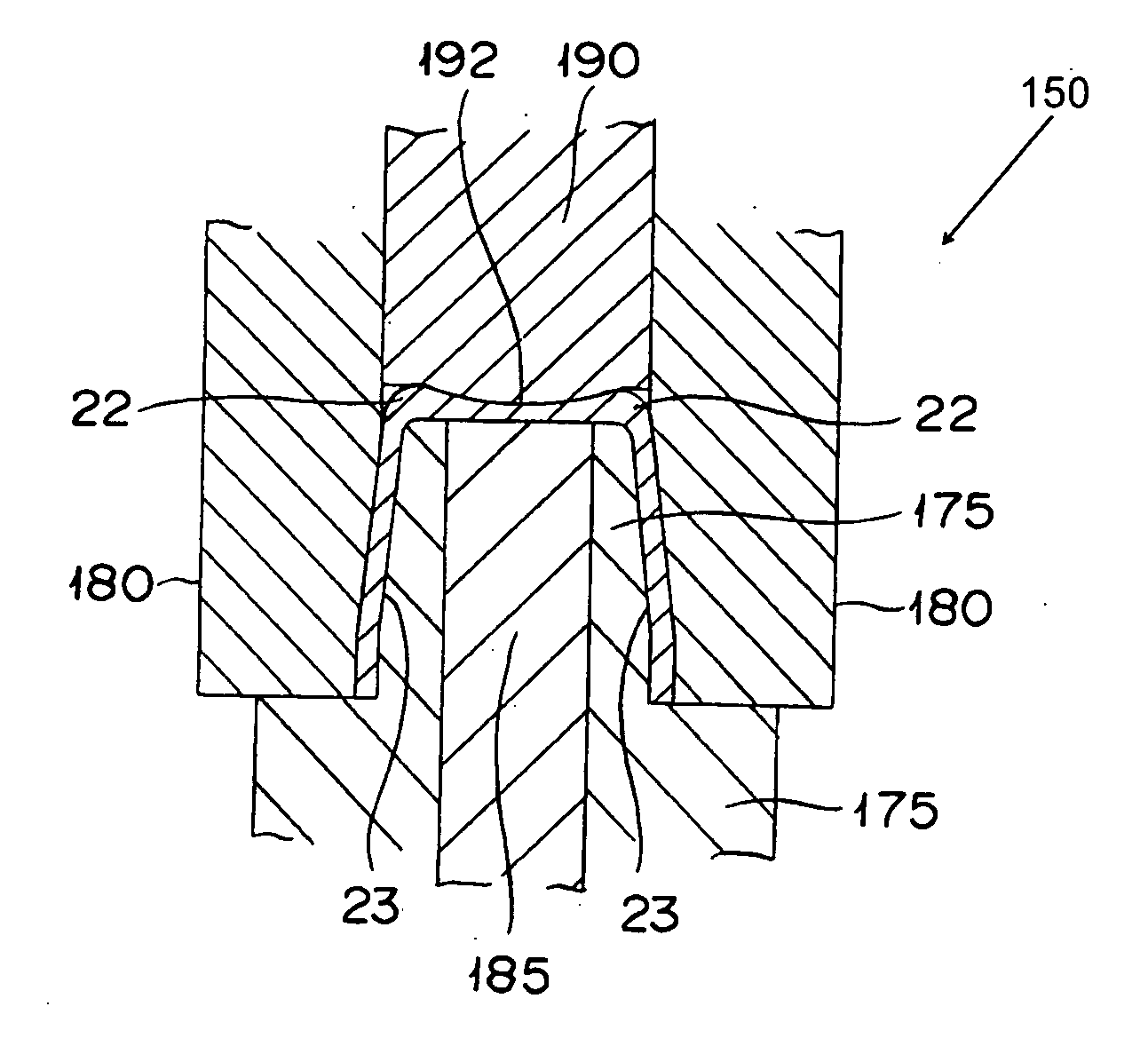
[0117]FIG. 22 is a partial cross sectional view of a thickness increasing device 450 of a press-formed member manufacturing apparatus in accordance with a fourth embodiment of the present invention. FIG. 23 is an enlarged partial cross sectional view of the thickness increasing device 450 illustrating flow of material in a corner portion of a press-formed member.

[0118] The third embodiment of the present invention differs from the third embodi...


PUM

PropertyMeasurementUnit
thicknessaaaaaaaaaa
pressureaaaaaaaaaa
shapeaaaaaaaaaa

Abstract

A press-formed member includes a first wall with a first thickness, a second wall with a second thickness, and a first corner portion. The first corner portion is disposed between the first and second walls, with the first corner portion having an increased thickness formed by pressure-forming such that the increased thickness of the first corner portion is larger than the first and second thicknesses of the first and second walls adjacent to the first corner portion. In a manufacturing method for the press-formed member, a preliminary body structure to be deformed is provided, and the thickness of the first corner portion of the preliminary body structure is increased by applying pressure to the preliminary body structure.

Description

CROSS-REFERENCE TO RELATED APPLICATIONS [0001] This application claims priority to Japanese Patent Application Nos. 2005-348083, filed on Dec. 1, 2005, and 2006-215960 filed on Aug. 8, 2006. The entire disclosures of Japanese Patent Application Nos. 2005-348083 and 2006-215960 are hereby incorporated herein by reference. BACKGROUND OF THE INVENTION [0002] 1. Field of the Invention [0003] The present invention relates to a press-formed member having a corner portion, a press-formed member manufacturing apparatus configured and arranged to manufacture the press-formed member having the corner portion, and a press-formed member manufacturing method for manufacturing the press-formed member having the corner portion. [0004] 2. Background Information [0005] Japanese Laid-Open Utility Model Application Publication No. 63-117606A discloses a conventional press-formed member including a bent portion (corner portion), such as a suspension part used in a vehicle. The conventional press-formed...

Claims


Application Information

Patent Timeline
Patent Type & Authority Applications(United States)
IPC IPC(8): B21D22/00
CPCB21D22/02B21D53/88
Inventor YOSHITOME, MASAAKIMATSUYAMA, HIDENOBUMATSUDA, SHINICHI
Owner NISSAN MOTOR CO LTD
Why Eureka
Try Eureka