Geothermal pipe weight

a geothermal well and pipe weight technology, applied in the direction of borehole/well accessories, domestic cooling apparatus, insulation, etc., can solve the problems of difficult inserting into straight-bore wells, reduce or even eliminate curvature, and reduce the rigidity of connections

Inactive Publication Date: 2007-05-08
MCNAIR EDWARD F +1
View PDF11 Cites 20 Cited by
  • Summary
  • Abstract
  • Description
  • Claims
  • Application Information

AI Technical Summary

Benefits of technology

[0019]Insertion of the geothermal system piping into the vertical well is made more difficult due to the pipe's shape memory. Because such piping is delivered on rolls, the pipe tends to retain some curvature. If the pipe is stretched out in the sun on a warm day, the curvature may be reduced or even eliminated, but the pipe also loses rigidity, making it difficult to work with. The weights described above may be configured to provide the straightness and rigidity needed to insert the pipe into the well.
[0020]Weights may be made in sections for ease of handling. The sections must be stackable in a fashion that provides rigidity to their joints, thereby making the whole substantially rigid. The weights are constructed with any of a number of various interlocking ends. The weights are typically affixed to the geothermal piping with tape. Tape at or near the ends of each weight help ensure the rigidity of the connections.

Problems solved by technology

Two problems present themselves when piping is inserted into a well for a ground-source heat pump system:1. The pipe, even filled with water, is buoyant in the contents (mud, sand, water, etc.) of the well, and may require significant force to keep it from floating back out of the well.2. The pipe, having been stored in a roll, retains some curvature making it difficult to insert into a straight-bored well.

Method used


Image

  • Geothermal pipe weight
  • Geothermal pipe weight
  • Geothermal pipe weight

Examples


second embodiment

[0044]the present invention is shown in plan view in FIG. 5 and perspective views in FIGS. 6a and 6b. In this case, the weight 500 has a special cross sectional shape to receive the geothermal pipes 110 and the tremie pipe 330. To define the cross sectional shape of the weight 500, we begin with a substantially square rectangle with rounded corners. Each of the four substantially equal sides is curved inward, toward the center of the rectangle in substantially circular arc shapes to receive the geothermal pipes 110 and tremie pipe 330. The shape described and illustrated is hereby defined as a modified receptive square.

[0045]In this embodiment, the geothermal pipes 110 are not separated by a web. These special weights 500 are stacked end to end in use and coupled by mating pins 510 with sockets 520. The special weight 500 is shown in FIG. 6a with no attached piping, while in FIG. 6b, the geothermal pipes 110 and the tremie pipe 330 are shown in dashed lines in position on the specia...

first embodiment

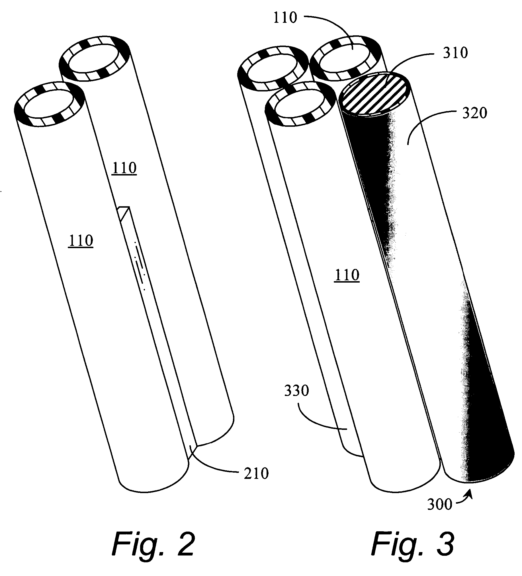
[0046]It is important that, whatever form the weights 300, 500 take, they may be coupled end to end such that some rigidity is imparted to the geothermal pipes 110. Some examples of such end couplings are illustrated in FIGS. 7–10 for the weight 300. A conical insert 710 is inserted into a matched conical socket 720 in FIG. 7. The weights 300 depicted in FIG. 7 have a ferrous material core 310 such as steel or cast iron coated with a water impervious coating 320 such as polyethylene; or the weights may be made of concrete with no coating. FIG. 8 depicts a weight 300 constructed by filling a DNR, NSF, and / or EPA (or similar) approved pipe 830 with sand or other dense material. The insert 810 and socket 820 are fittings—threaded or glued onto the pipe 830.

[0047]A system for threading the weights 300 together is shown in FIG. 9. A male thread 910 is provided at one end of the weight 300 while a female bushing 920 is used at the other end of the weight 300.

[0048]A right circular cylindr...

third embodiment

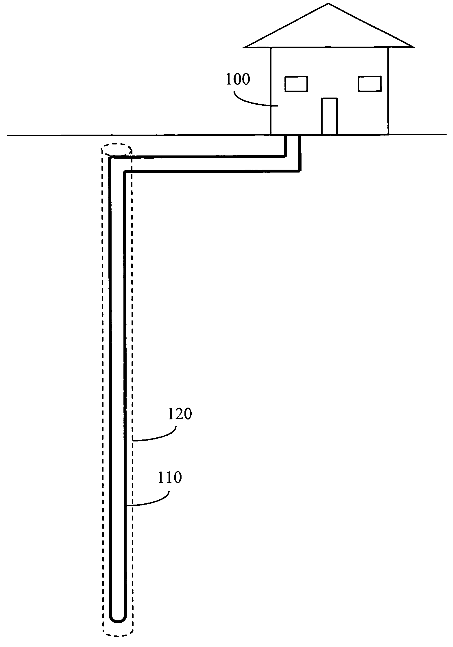
[0050]the present invention is shown in FIG. 12. A weight 1200 hangs from a hanger 1210 attached to an elbow 1220 at the bottom of the geothermal pipes 110. A rope or coated metallic wire or cable is used to attach the weight 1200 to the hanger 1210 via a loop 1240 made fast to the concrete weight. The loop is also made of rope or coated metallic wire or cable. The weight may, again, be made of steel or iron coated with a water impervious material to be approved by the DNR, NSF and / or EPA (or equivalent); or it may be of concrete, which does not need a coating.


PUM


Abstract

A method and apparatus for adding rigidity and weight to the piping used in geothermal wells for ground-source heat pumps enhances insertion of the piping into the wells. The weight used must be approved by appropriate organizations such as the DNR, NSF, and / or EPA, or similar, for contact with the ground water. Concrete and coated iron or steel are examples of such weights. A system for assembling the pipes, weight, and a tremie pipe for insertion is disclosed. The weighting system may also help maintain straightness in the geothermal piping for ease of inserting the piping into the vertical well.

Description

CROSS REFERENCE TO RELATED APPLICATIONS[0001]Not applicable.STATEMENT REGARDING FEDERALLY SPONSORED RESEARCH OR DEVELOPMENT[0002]Not applicable.REFERENCE TO MICROFICHE APPENDIX[0003]Not applicable.BACKGROUND OF THE INVENTION[0004]1. Field of the Invention[0005]The present invention relates generally to an apparatus for geothermal wells. More specifically, the present invention relates to a method and apparatus for providing weight and rigidity to the piping used in vertical wells drilled for ground-source heat pumps. The invention is used to aid in inserting the piping, along with a tremie pipe, into the well.[0006]2. Background Art[0007]Heat pumps typically exchange heat between an indoor space and the ambient. The coefficient of performance for both the heat pump cycle as well as the refrigeration cycle is usually significantly enhanced by using ground water for the ambient because the temperature of the ground water is fairly constant at temperatures often closer to the desired i...

Claims


Application Information

Patent Timeline
Patent Type & Authority Patents(United States)
IPC IPC(8): F28F1/00F25B27/00F28D7/06E21B43/10E21B43/24F24J3/08F25B30/06
CPCE21B43/10F24J3/083F25B30/06Y02E10/125F24T10/15Y02E10/10
Inventor MCNAIR, EDWARD F.BURHANS, RICHARD C.
Owner MCNAIR EDWARD F
Why Eureka
Try Eureka