

Scanning mirror
a scanning mirror and mirror technology, applied in the field of scanning mirrors, can solve the problems of difficult to enhance energy density, shorten service life, and difficult to apply laser beams to a wide region, and achieve the effects of reducing the moment of inertia of the scanning mirror, reducing the moment of inertia, and small effective reflection rang
Active Publication Date: 2018-11-06
DISCO CORP
View PDF5 Cites 0 Cited by
- Summary
- Abstract
- Description
- Claims
- Application Information
AI Technical Summary
Benefits of technology
The present invention provides a scanning mirror that can prevent flexure of the mirror base during high-speed driving, resulting in better focusing performance and a larger effective reflection range. The scanning mirror is made from a non-metallic material with a specific rigidity, which allows for a smaller size, increased flexibility, and reduced cost. The invention also enables the use of a larger beam diameter processing laser beam and enhances energy density, leading to finer and wider-range processing.
Problems solved by technology
As a result, bad influences such as shortening of service life due to accumulation of damages or a thermal lens effect may be exerted on optical elements such as mirrors or lenses for guiding light to the scanning mirror.
Besides, as the beam diameter of the laser beam is reduced, numerical aperture (NA) is lowered, which would make it difficult to enhance energy density and to apply the laser beam to a wide region.
Since quartz glass used conventionally is not a material that has a sufficient rigidity, flexure may be generated in the mirror base formed from quartz glass at the time of high-speed driving, leading to a lowered focusing characteristic.
This problem becomes more conspicuous as the effective reflection range of the scanning mirror is enlarged, and as the scanning mirror is driven at a higher speed and in a wider angle.
Method used
View moreImage
Smart ImageViewing Examples

Examples
example 4
[0039]In Example 4, sapphire having a specific rigidity of 87.5 GPa·cm3 / g was used as material for the mirror base 16. The other conditions were the same as in Example 1.
example 1
PRIOR ART EXAMPLE 1
[0040]In Prior Art Example 1, quartz glass having a specific rigidity of 32.7 GPa·cm3 / g was used as material for the mirror base 16. The other conditions were the same as in Example 1.
example 5
[0041]In Example 5, the mirror base 16 was excited at an excitation frequency of 10 kHz and with a mechanical deflection angle of π / 360 rad. The value of f2·θ in this case is 873 krad / s2. The other conditions were the same as in Example 1.
Login to View More PUM
| Property | Measurement | Unit |
|---|---|---|
| frequency | aaaaa | aaaaa |
| thickness | aaaaa | aaaaa |
| thickness | aaaaa | aaaaa |
Abstract
A scanning mirror includes a mirror base and a reflective film formed on the mirror base. The mirror base is formed from a non-metallic material having a specific rigidity, determined by Young's modulus (GPa) and density (g / cm3), of at least 100 GPa·cm3 / g.
Description
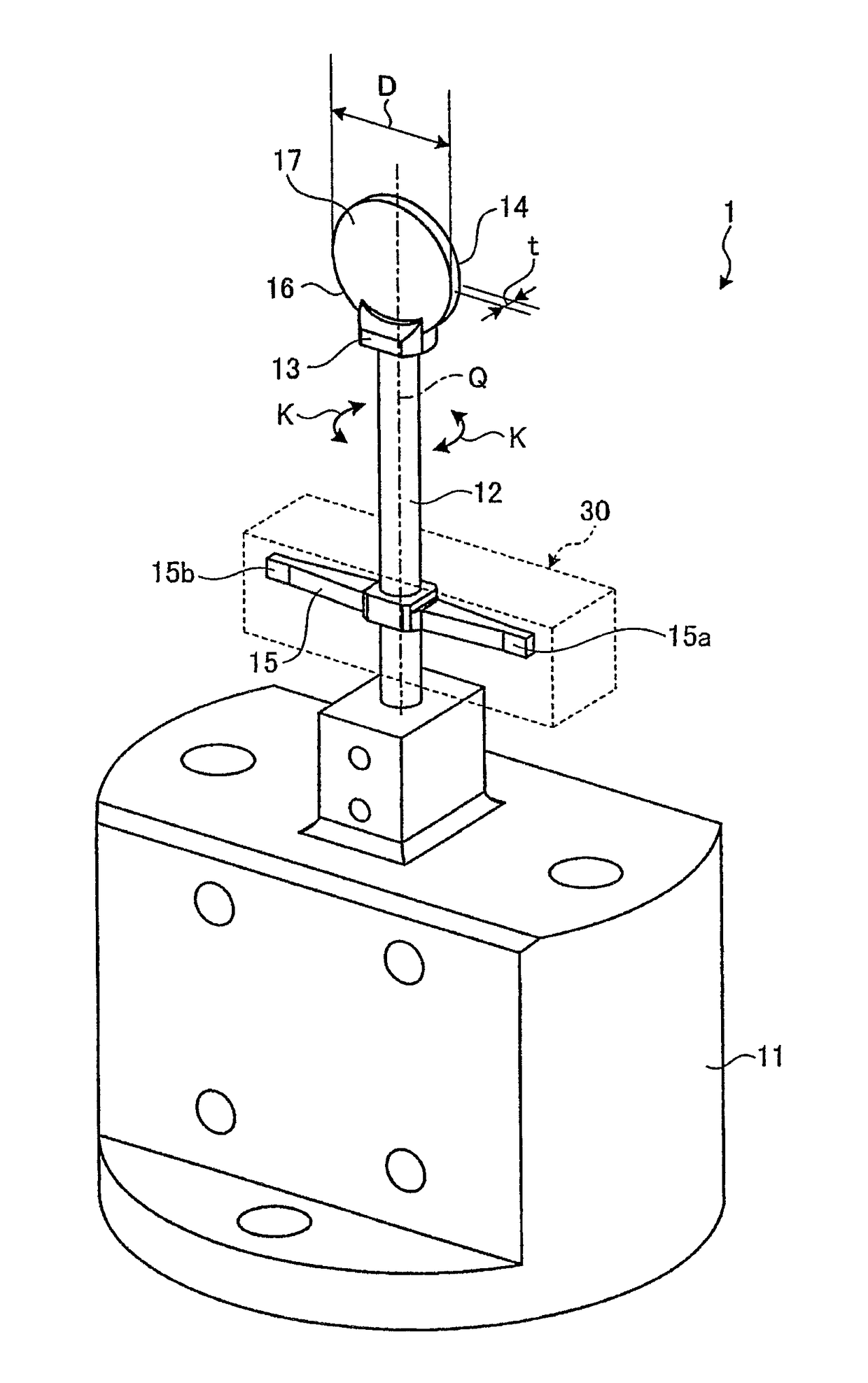
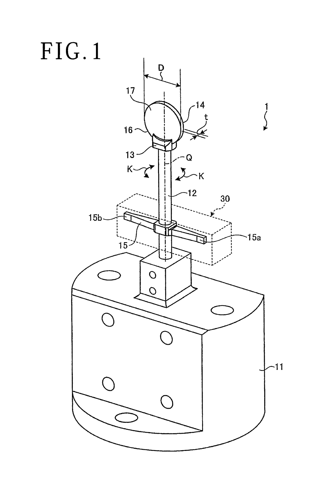
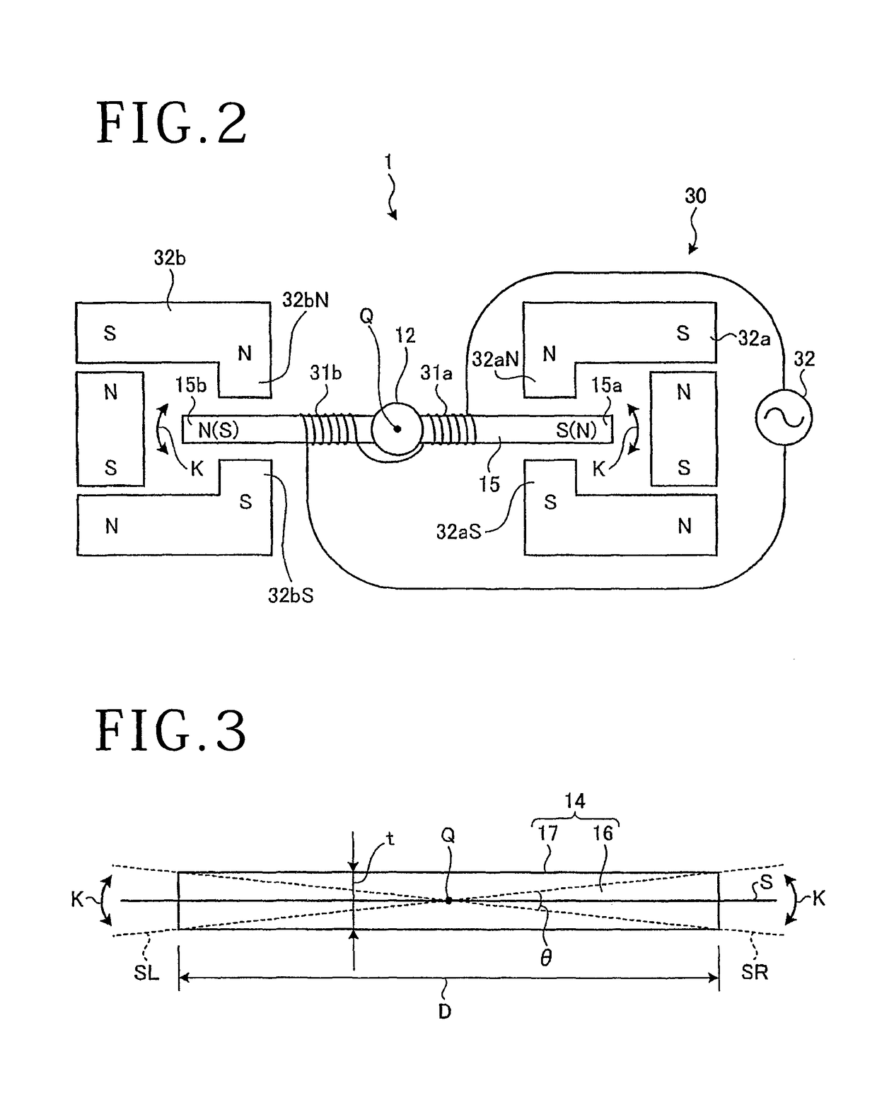
BACKGROUND OF THE INVENTION[0001]Field of the Invention[0002]The present invention relates to a scanning mirror.[0003]Description of the Related Art[0004]In laser scanning type confocal microscopes and the like, in general, a scanner apparatus, such as a galvano scanner and a resonant scanner, that has a scanning mirror is used. In addition, in the semiconductor device manufacturing process, formation of through-holes by applying a laser beam is conducted. For forming a multiplicity of through-holes at a high speed, a technology has been proposed in which formation of through-holes is performed while driving (exciting) a scanning mirror about an axis of a scanner apparatus at a high speed to deflect the direction of a laser beam at a high speed (see, for example, Japanese Patent Laid-open No. 2008-068270). In this type of scanning mirrors, conventionally, quartz glass is used as material for a mirror base, and a thin film of a metal such as aluminum or a multilayer film of a dielect...
Claims
Login to View More Application Information
Patent Timeline
 Patent Type & AuthorityPatents(United States)
IPC IPC(8): G02B26/10G02B5/08
CPCG02B5/0808G02B26/105B23K26/082G02B21/0048
InventorKUDO, YU
OwnerDISCO CORP