
Automatic focusing method

a focusing method and automatic technology, applied in the direction of optical radiation measurement, focusing aids, instruments, etc., can solve the problems of manual focusing, affecting the accuracy of the measurement system, and difficult to find and define the optimal focusing position, so as to reduce the time required, eliminate the possibility of manual focusing errors, and simple and fast

Inactive Publication Date: 2007-04-05
CHROMA ATE
View PDF3 Cites 3 Cited by
  • Summary
  • Abstract
  • Description
  • Claims
  • Application Information

AI Technical Summary

Benefits of technology

[0008] In order to overcome the shortcomings and drawbacks of the prior art, the present invention provides a simple, speedy and highly accurate automatic focusing method for use in an interferometer, so that the results of focusing process will not be affected by the undulation of the curve of the focusing function, hereby achieving the objective of obtaining the optimal focusing position, effectively reducing the time required for the measurement preparation of the interferometer, and eliminating the possibility of manual focusing errors.
[0009] An another objective of the present invention is to provide an automatic focusing method, that can be used to perform 3-D measurement by making use of the white light interference technology, so as to scan the entire wave-packet area and accurately achieve the optimal focusing and effective scan range, while reducing the undesirable noise to the minimum and raising the measurement efficiency. As such, realizing the setting of the optical focal point as the center of scanning range, so that the measurement errors are reduced and the measuring data can be more accurate and convincing.

Problems solved by technology

Since the correct focusing of the interferometer is essential to the quality of the interference fringes produced, thus indirectly affecting the accuracy of the measurement system, thus the focus position of the imaging system must first be adjusted properly before the measurement can be implemented.
As mentioned earlier, the curve of the focusing function of the interferometer is not a simple curve having the maximum value at its single peak, it is rather provided with the wave-packet like undulations, so that it would be very time consuming if its focusing is done manually.
In terms of accuracy, in case that the manual adjustment of the focus position is based on the judgment of a naked eye, then quite often the optimal focusing position is not easy to find and define.
In terms of reproducibility, the manual determination and adjustment of the optimal focusing position is not liable to have consistent results.
However, the major drawback of this conventional method of automatic focusing is that, even if the position to be searched is already in the wave packet area, it is still required to search back-and-forth to find and define the boundary of the wave packet area, so this kind of automatic focusing is pretty time consuming, besides, its search is restricted to the surrounding of the wave packet area, thus the search area is rather limited.
Moreover, some of the conventional technologies require the use of additional hardware to achieve the objective of automatic focusing, thus additional hardware arrangement must be provided to the interferometer, or the focusing operation may be performed only when sufficient information of wave packet area is provided, thus the search process is rather time consuming and is not suitable for large area automatic focusing.

Method used


Image

  • Automatic focusing method
  • Automatic focusing method
  • Automatic focusing method

Examples


Embodiment Construction

[0021] The purpose, construction, features, and functions of the present invention can be appreciated and understood more thoroughly through the following detailed description with reference to the attached drawings.

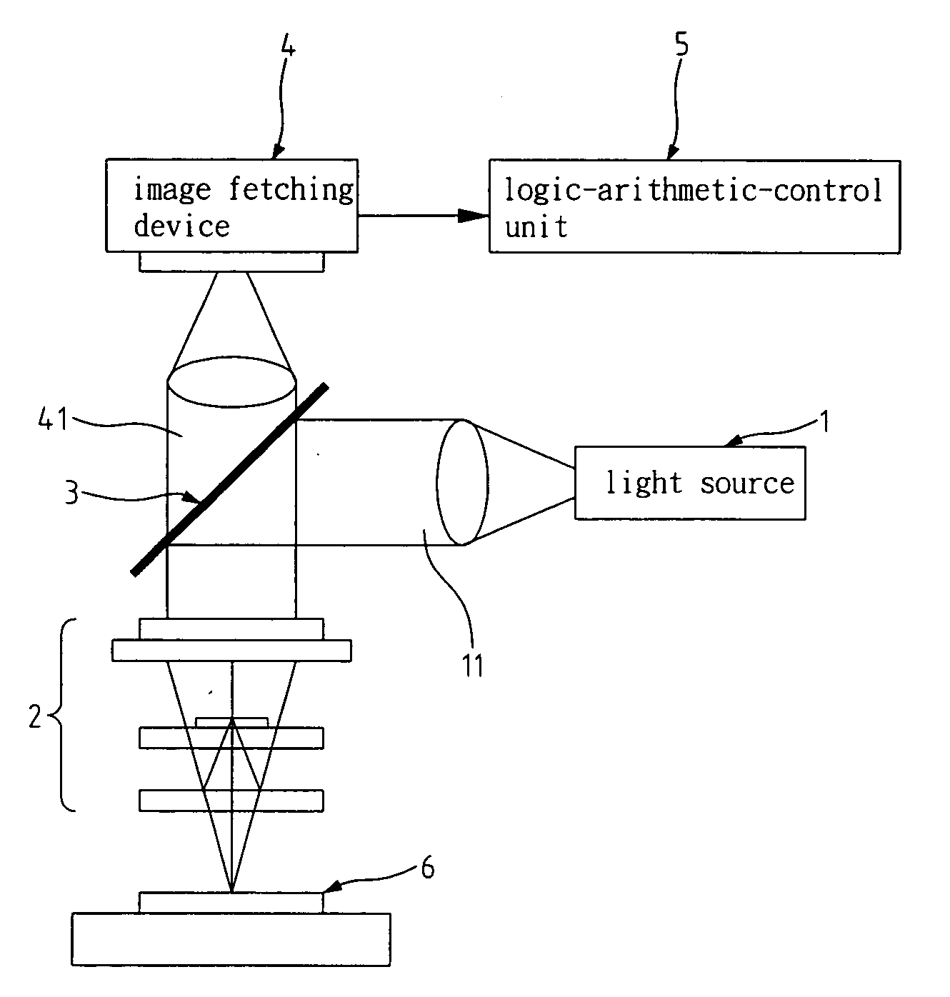
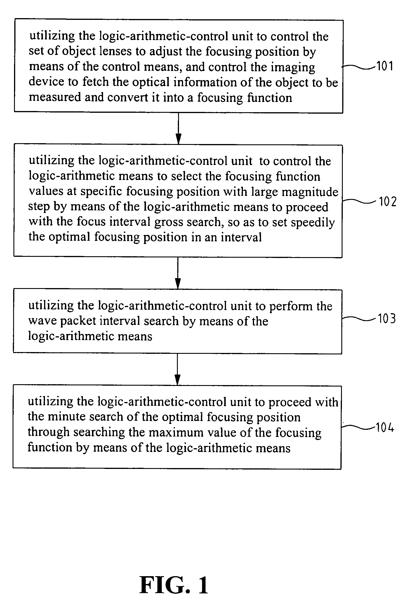
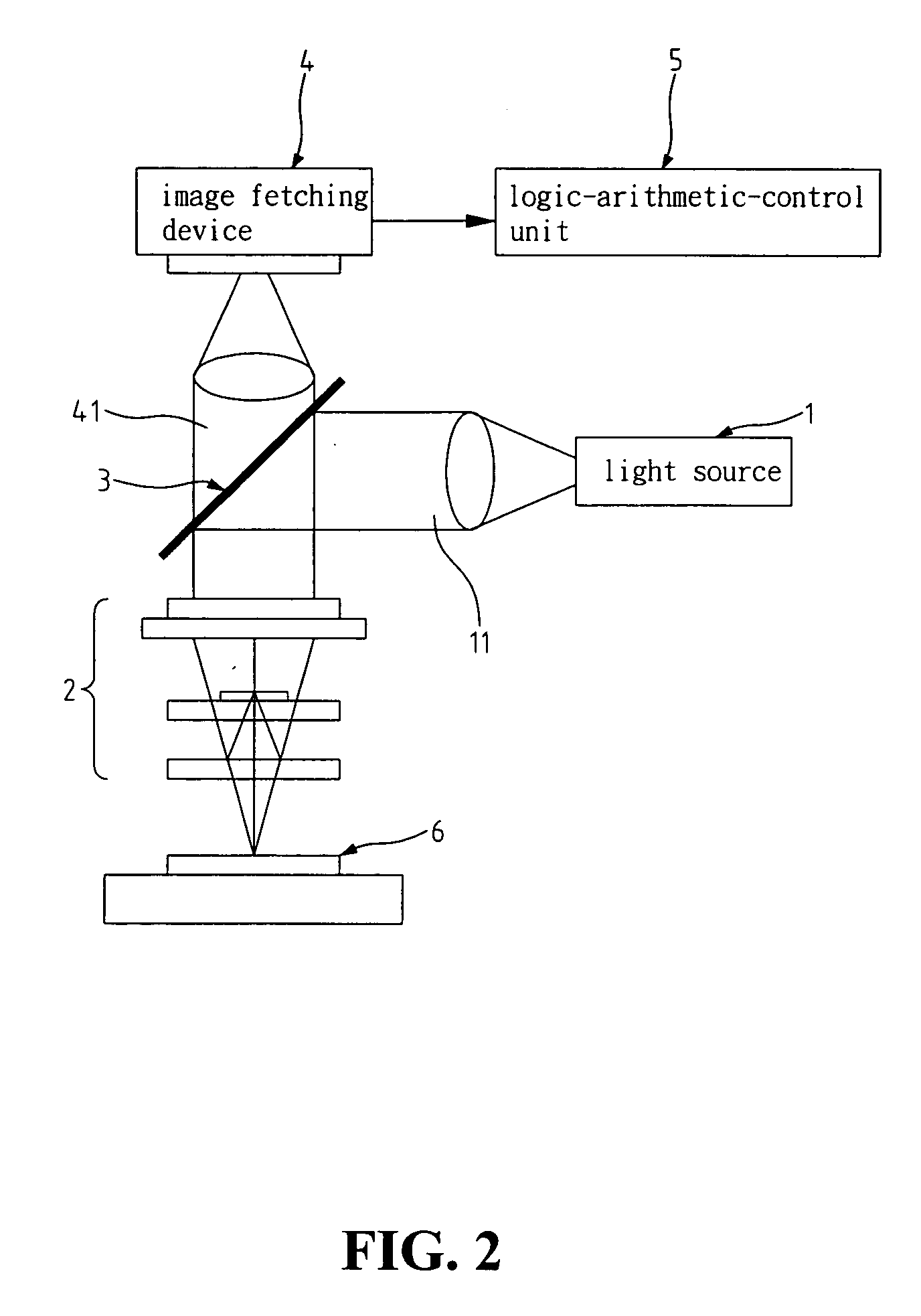
[0022] Firstly, referring to FIGS. 1 to 3. FIG. 1 is a flowchart of the steps of the automatic focusing method according to an embodiment of the present invention. FIG. 2 is a schematic diagram of the structure of interferometer used in realizing the automatic focusing method of the present invention. FIG. 3 is a diagram indicating the distribution of the focusing function values vs the focusing positions obtained by the automatic focusing method of the present invention. According to FIGS. 1 & 2, the present invention relates to an automatic focusing method for the image fetched by an optical image system. As shown in FIG. 2, the optical image system includes: a light source 1, a set of object lenses 2, a light splitter 3, an imaging device 4, and a logic-arithmetic-co...


PUM


Abstract

An automatic focusing method is provided, which is realized through an imaging device as based on the multi-stage search principle and a focusing function. Thus the focusing position search is implemented in three stages of: the optimal focusing position gross search, the wave packet interval search, and the optimal focusing position minute search, with the respective stages having different search-step-magnitudes. Wherein, the integer times of one half the wavelength of the incident light of the imaging device is utilized as the search-step-magnitude to search for the maximum value of the focusing function in the wave packet interval, and define the focusing position corresponding to the maximum value of the focusing function as the optimal focusing position, hereby obtaining the optimal focusing position in a speedy and efficient manner.

Description

BACKGROUND OF THE INVENTION [0001] 1. Field of the Invention [0002] The present invention relates to an automatic focusing method for imaging devices, and in particular to a focus determination and adjustment method used in an imaging device to achieve the automatic focusing of the object to be measured, of which an image is to be taken. [0003] 2. The Prior Arts [0004] In the conventional imaging system, the automatic focusing is utilized to adjust the focal length of a set of optical lenses thus to get a clear and accurate image. Usually, in the implementation of this technology, the curve of the focusing function for an imaging system is a single peak curve which changes its value along the focusing axis of a set of optical lenses, so that the maximum value of the function corresponds to the optimal focusing position defined by the system. However, for the interferometer, the curve of its focusing function is represented by the superimposition of the single peak curve of an imagin...

Claims


Application Information

Patent Timeline
IPC IPC(8): G02B7/04G03B17/00G02B27/40
CPCG01J1/04G01J1/0448G03B13/36
Inventor LIAO, CHIEH-CHENGLIN, YAO-MIN
Owner CHROMA ATE
Learn More