Brake disk producing method and brake disk

a technology of brake disk and producing method, which is applied in the direction of braking disc, metal-working feeding device, handling device, etc., can solve the problems of increased processing cost of molding the brake disk, increased processing cost of the brake disk, and significant wear of the brake pad, so as to prevent non-uniform wear, reduce the amount of wear, and improve heat radiation capability

Active Publication Date: 2011-01-27
SUNSTAR GIKEN KK
View PDF9 Cites 0 Cited by
  • Summary
  • Abstract
  • Description
  • Claims
  • Application Information

AI Technical Summary

Benefits of technology

[0018]The method of producing a brake disk according to the present invention is a method of producing a brake disk rotating integrally with a wheel, comprising an outer periphery pressing step for forming an outer peripheral shape of a rotor plate of the brake disk into a shape having recesses and ridges repeated in the radial direction by means of press molding, and a chamfering step for forming a chamfered surface on the rotor plate having the repeated shape molded in the outer periphery pressing step, by pressing, against a corner portion on an outer peripheral edge of the rotor plate having the repeated shape, a die provided with an inclined surface contacting with the corner portion in accordance with the repeated shape, and by plastically deforming the corner portion. Therefore, by means of the outer periphery pressing step, the repeated shape of recesses and ridges in the radial direction can be processed using a pressing device and the processing time can be reduced, thus it is possible to realize a brake disk capable of improving heat radiation capability, reducing the weight thereof, reducing moment of inertia, and suppressing increase in production costs. In addition, by means of the chamfering step, a chamfered surface can be molded on the rotor plate having the repeated shape by using a pressing device and the processing time can be reduced, thus it is possible to realize a brake disk capable of improving safety in handling and controlling production costs. Also, the amount of wear of a brake pad pressed by the brake disk is suppressed by forming the chamfered surface, so that durability of braking performance can be improved. Moreover, a brake disk capable of improving design can be realized by means of an external appearance of the repeated shape of recesses and ridges and of the chamfered surface.
[0029]In addition, in the brake disk, a chamfered length from the corner portion on the outer peripheral edge of the rotor plate toward a direction of a surface contacting with the brake pad, and a chamfered length from the corner portion toward a direction of an outer peripheral end surface are greater than or equal to 0.1 mm and less than or equal to 2.0 mm, preferably greater than or equal to 0.1 mm and less than or equal to 1.0 mm, or more preferably greater than or equal to 0.2 mm and less than or equal to 0.7 mm. Hence, the effect of preventing nonuniform wear of the brake pad pressed by the brake disk, and the effect of reducing the amount of wear become significant.

Problems solved by technology

Although the brake disk, whose outer peripheral shape is formed to have recesses and ridges repeated in the radial direction, is preferred in terms of its improved heat radiation capability, light-weight body, improved design and the like, the brake disk with such outer peripheral shape has problems that the brake pad wears out significantly and the processing cost for molding the brake disk rises.
Particularly, in a case of forming a chamfered surface at a corner portion of an outer peripheral edge of the brake disk out of consideration for safety, design and the like, the processing for the formation needs to be carried out for a long period of time using an expensive processing machine or special processing machine such as an NC machining tool or the like since the outer peripheral shape is formed to have recesses and ridges repeated in the radial direction.
Therefore, the processing cost for the formation of a chamfered surface increases significantly.
For this reason, the brake disk, whose outer peripheral shape is formed to have recesses and ridges repeated in the radial direction, comprises the characteristics of the improved heat radiation capability, the light weight body, the improved design and the like, but has, on the other hand, a problem that such brake disk lacks practicability due to the poor durability of the braking performance and high production costs.

Method used


Image

  • Brake disk producing method and brake disk
  • Brake disk producing method and brake disk
  • Brake disk producing method and brake disk

Examples


Embodiment Construction

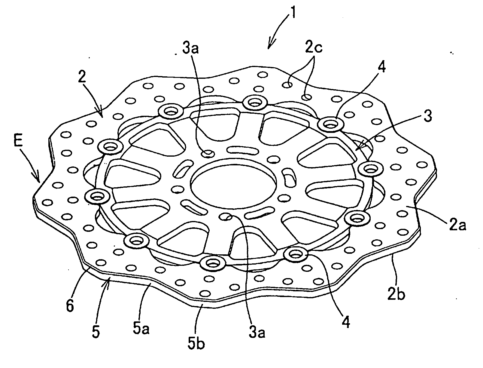
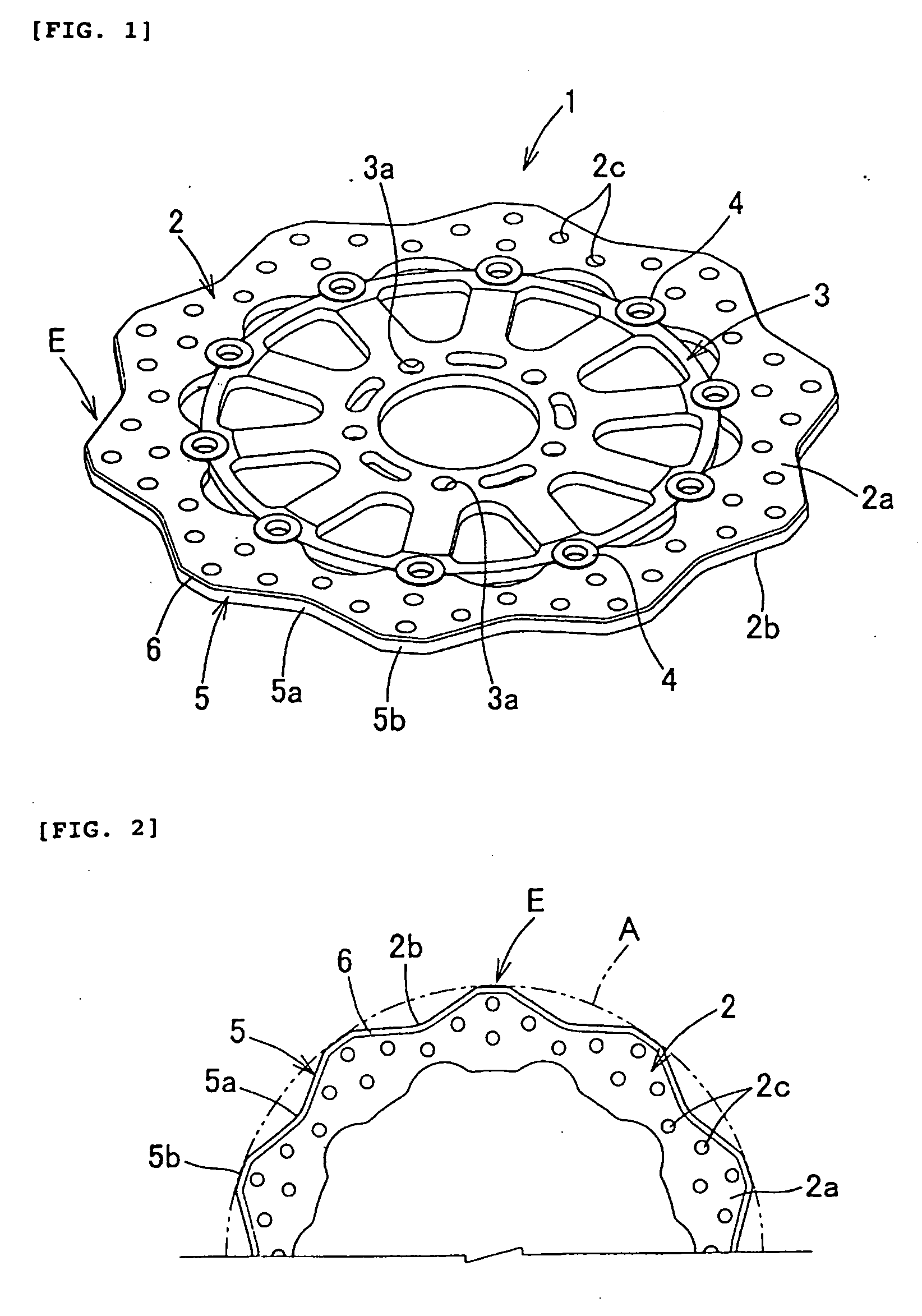
[0038]FIG. 1 is a perspective view showing a configuration example of a brake disk according to an embodiment of the present invention, wherein a floating brake disk is shown. The brake disk 1 comprises an outer rotor plate 2, an inner rotor plate 3 provided with attached holes 3a, 3a, . . . for a wheel which is not shown, and a floating pin 4, 4, . . . connecting the outer rotor plate 2 and the inner rotor plate 3. Only the inner rotor plate 3 is fixed to the wheel by means of the attached holes 3a, 3a, . . . by using bolts, and the outer rotor plate 2 is not fixed to the wheel. In this manner, the inner rotor plate 3 which is a portion attached to the wheel and the outer rotor plate 2 which is a friction portion against which an unshown brake pad is pressed are independent from each other, so that distortion of the outer rotor plate 2 caused by telescopic deformation of the outer plate 2 by the frictional heat can be suppressed. Therefore, this brake disk 1 is characterized in tha...


PUM

PropertyMeasurementUnit
lengthaaaaaaaaaa
lengthaaaaaaaaaa
lengthaaaaaaaaaa

Abstract

A brake disk producing method, comprising a periphery pressing step for forming an outer peripheral shape (5) of a rotor plate (2) into a peripheral shape having recesses and ridges (5a, 5b) repeated in a radial direction, and a chamfering step for forming a chamfered surface (6) by pressing, against a corner portion (2d) on an outer peripheral edge of the rotor plate (2), a die (7), and a brake disk made by the method. Accordingly, it is possible to improve heat radiation capability, reduce the weight and moment of inertia, improve safety in handling, and suppress increase in production costs. Furthermore, by forming the chamfered surface (6), the amount of wear of a brake pad pressed by the brake disk (1) can be reduced, and durability of braking performance can be maintained or improved.

Description

RELATED APPLICATIONS[0001]This application is a division of U.S. patent application Ser. No. 10 / 581,313, filed Jun. 2, 2006, which application claims priority of Japanese Application No. 2003-403674, filed Dec. 2, 2003, the entire contents of which are incorporated herein by reference.TECHNICAL FIELD[0002]The present invention relates to a method of producing a brake disk whose outer peripheral shape is formed to have recesses and ridges repeated in the radial direction and to the improvement of the brake disk, in a brake disk of a disk brake device used in a motorcycle and the like.BACKGROUND ART[0003]Because of its compact size, light weight, large absorbed energy and stable braking force, a disk brake device is used widely as a brake device for a motorcycle, a car, a pickup truck, or the like (see Japanese Patent Application Laid-Open No. 2003-74604, for example). As the main component of such disk brake device, there is a brake disk. The brake disk rotates integrally with a whee...

Claims


Application Information

Patent Timeline
Patent Type & Authority Applications(United States)
IPC IPC(8): B21D43/28F16D65/12
CPCF16D65/12F16D2065/026F16D2065/1316F16D2069/004F16D2200/0017F16D2200/003F16D2250/0023F16D2065/1392
Inventor TAKENAKA, TADASHITAMURA, KOJI
Owner SUNSTAR GIKEN KK
Why Eureka
Try Eureka