Viscoelastic transmission device for a roller shutter actuator

a transmission device and roller shutter technology, applied in the direction of curtain suspension devices, curtain accessories, building components, etc., can solve the problems of poor material vibrational energy dissipation ability, limited shear load transmission, and increased stock items that are all the more troublesom

a transmission device and roller shutter technology, applied in the direction of curtain suspension devices, curtain accessories, building components, etc., can solve the problems of poor material vibrational energy dissipation ability, limited shear load transmission, and increased stock items that are all the more troublesom

US8464776B2Inactive Publication Date: 2013-06-18SOMFY SAS

Image

  • Viscoelastic transmission device for a roller shutter actuator
  • Viscoelastic transmission device for a roller shutter actuator
  • Viscoelastic transmission device for a roller shutter actuator

Examples


Embodiment Construction

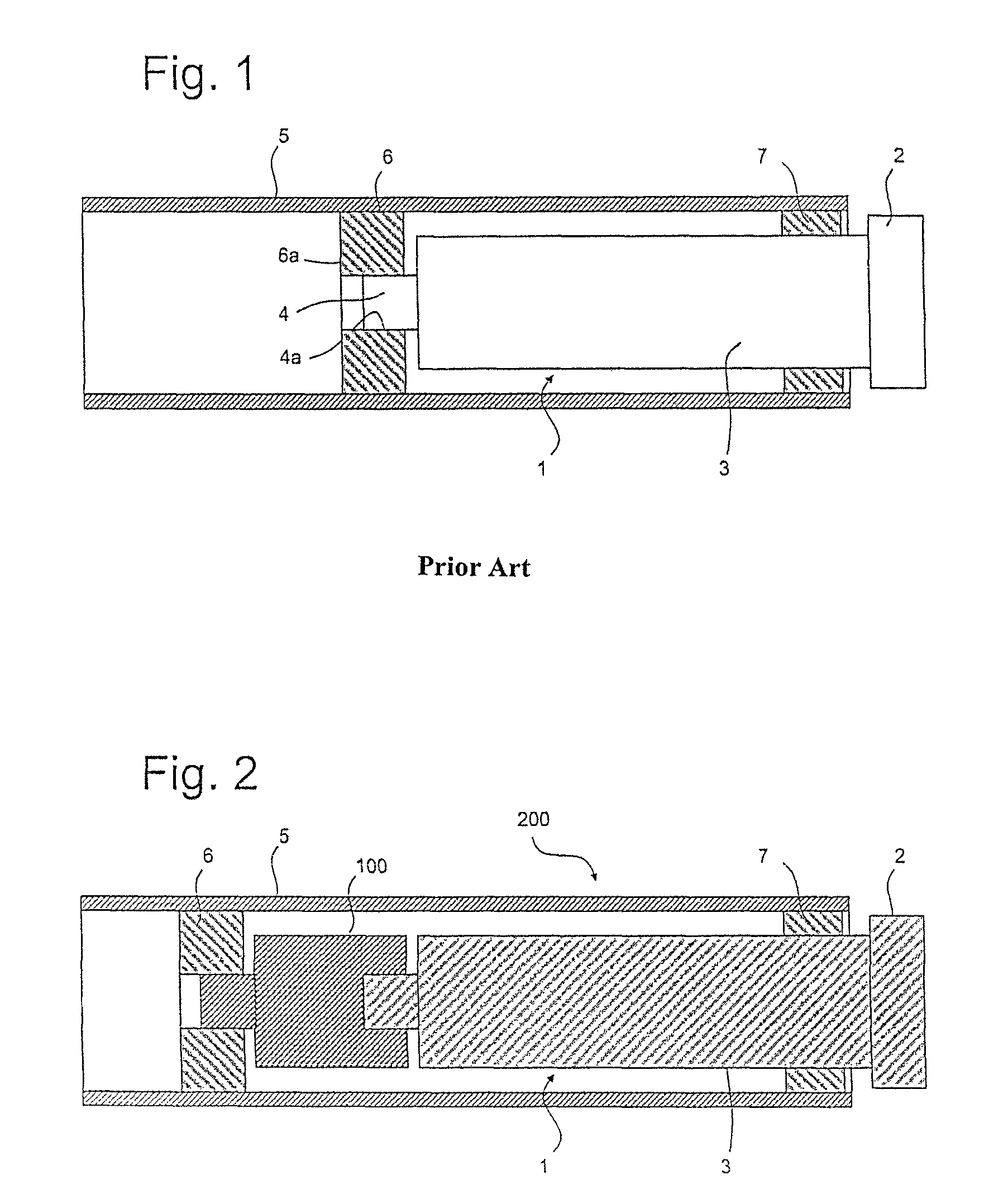
[0034]FIG. 1 is a cross section of an installation according to the prior art. The installation comprises a roll-up element of a building, such as a blind, an apron of a roller shutter, a screen, not depicted, that can be wound around a winding tube 5, as described in U.S. Pat. No. 4,159,162.

[0035]An electric actuator 1 comprises a fixed end 2, fixed to a rigid structure of the framework. The electric actuator comprises an actuator tube 3 comprising a motor and reduction gearing, neither depicted, an output shaft 4 able to rotate, engaged in a driving wheel 6 itself prevented from rotating with respect to the winding tube 5. An adapter ring 7, able to rotate with respect to the actuator tube 3, acts as a bearing for the winding tube.

[0036]An external profile 4a of the output shaft 4 and a recess 6a of the driving wheel 6 have interlocking shapes. Likewise, an external profile of the driving wheel and an internal profile of the winding tube have interlocking shapes.

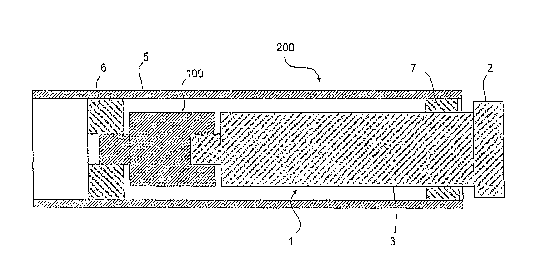
[0037]FIG. 2 is a ...


PUM


Abstract

Viscoelastic transmission device (100) for a mechanical connection between a shaft (4) of an actuator the axis (XX′) of which defines an axial direction, and a driving wheel (6) of a winding tube (5) of a blind, of a roller shutter or of a roll-up screen, which comprises a first component (10) that has an output profile that complements an input profile of a second component of the device, the first and the second components adhering to an intermediate component (30) made of viscoelastic material.

Description

BACKGROUND OF THE INVENTION[0001]The invention relates to a viscoelastic transmission device which, inside a winding tube for a blind, for a roller shutter or for a roll-up screen, provides the mechanical connection between the shaft of an actuator and a driving wheel that drives the winding tube.[0002]Winding tubes are not standardized. They have a wide variety of cross sections (circular, pentagonal, hexagonal, octagonal, etc.) and dimensions in an orthogonal cross section.[0003]A driving wheel according to the prior art comprises a housing able to accept an output shaft of the actuator and comprises an exterior profile able to fit inside the winding tube, with a limited clearance between the exterior profile of the wheel and the interior profile of the winding tube.[0004]For one same type of actuator, there are therefore a great many driving wheels, differing only in terms of their exterior profile, each wheel being able to collaborate with one specific winding tube.[0005]In orde...

Claims


Application Information

Patent Timeline
18 Jun 2013
Publication
US8464776B2
IPC
E06B9/72
CPC
E06B9/72; F16D3/68; F16D1/101; F16D2001/103
Inventors
ANTHOINE, SEBASTIEN