Portable footrest

a footrest and portability technology, applied in the field of portability, can solve problems such as increasing costs, and achieve the effect of expanding the width of the top pla

Inactive Publication Date: 2013-06-18
KIM JUNG EUNG
View PDF36 Cites 16 Cited by
  • Summary
  • Abstract
  • Description
  • Claims
  • Application Information

AI Technical Summary

Benefits of technology

[0011]The portable footrest according to the present invention is advantageous in that sliders are arranged at both sides of the top plate to extend the width of the top plate, and the width of the portable footrest is same or smaller than that of the top plate to allow for convenience of carry.

Problems solved by technology

The thus-configured footrest has drawbacks in that the top plate 10 has a fixed width which is deficient in providing proper or comfortable support for a user who has long legs or wide thighs or for a user who needs comfortable support while relaxing.
Moreover, the above-described conventional footrest employs hinges 12, which increases costs.

Method used


Image

  • Portable footrest
  • Portable footrest
  • Portable footrest

Examples


Embodiment Construction

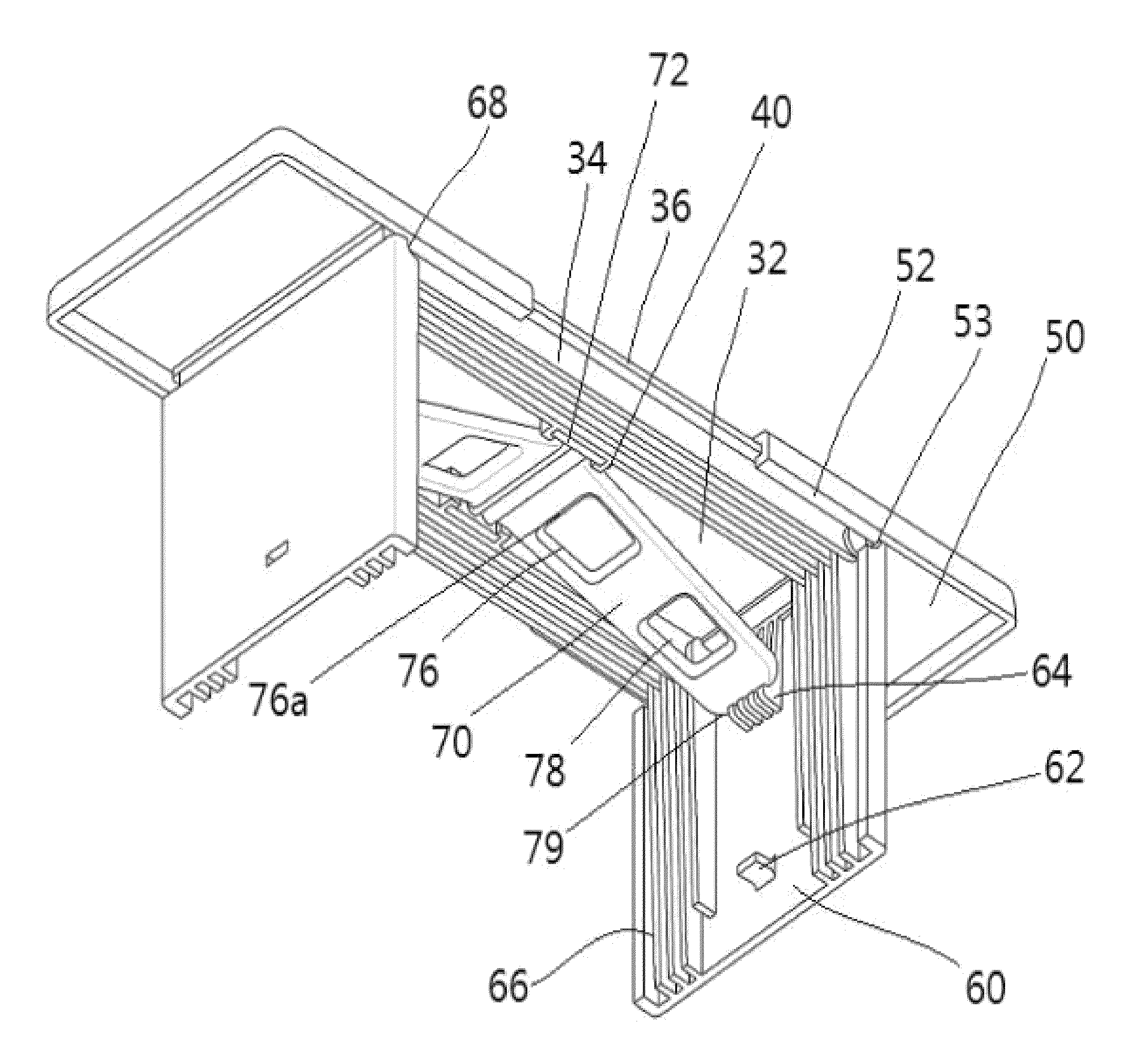
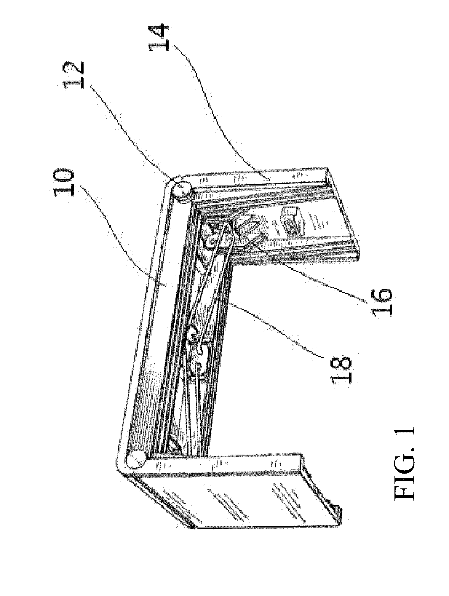
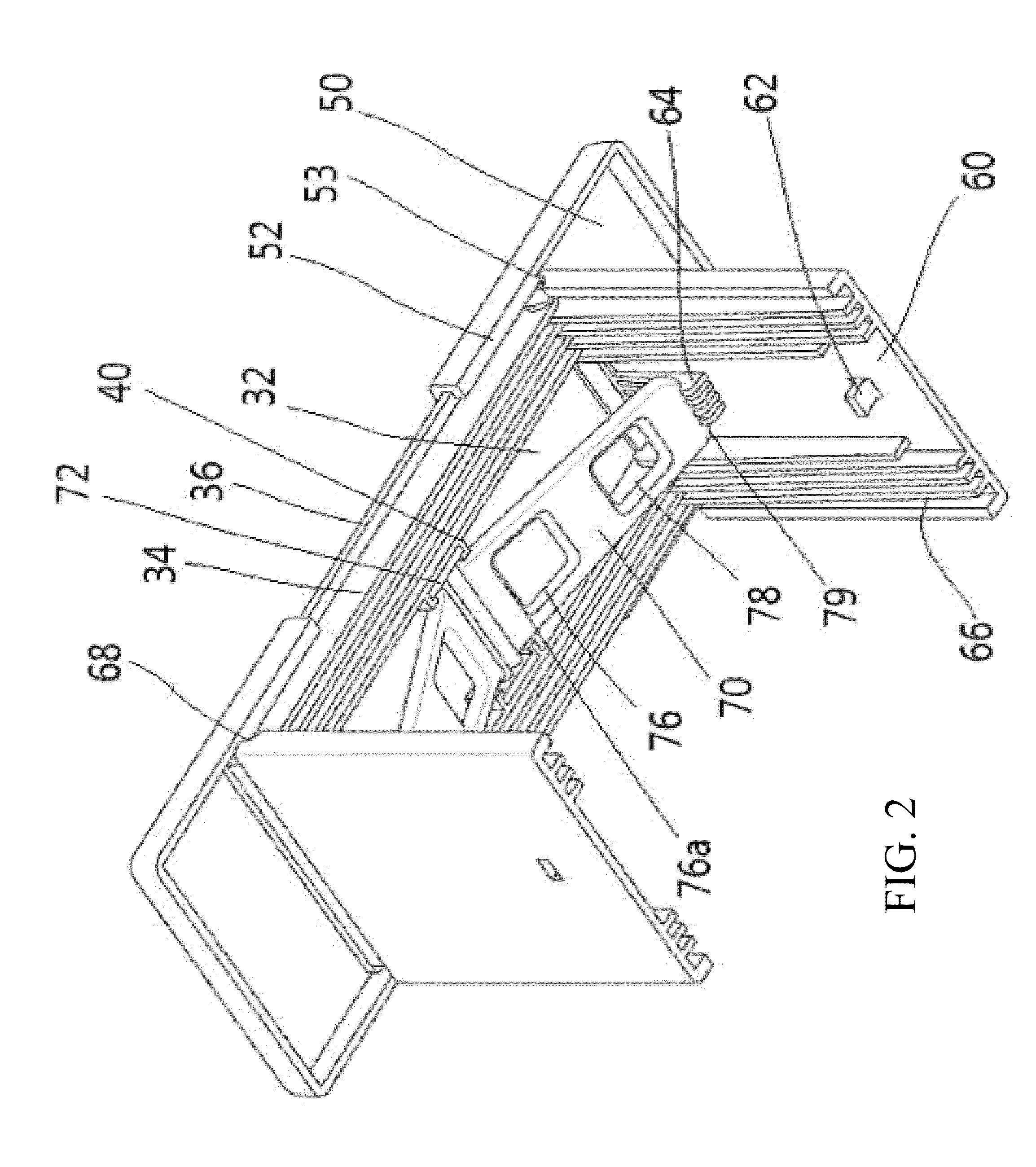
[0018]A footrest of the present invention comprises a top plate 32, a slider 50 which is arranged slidably on the top plate 32, a leg 60 which supports the top plate 32, and a support 70 for maintaining the leg 60 at an upright state.

[0019]The top plate 32 has a plurality of ribs 34 formed in a lengthwise direction thereof, and each of the ribs 34 has both ends with respective holes 35. The innermost rib has a receiving portion 40.

[0020]Referring to FIG. 3, the top plate 32 has pairs of closing holes 45 and extension holes 44 formed by regular spacing and arranged symmetrically with each other.

[0021]The slider 50 has a square C-shaped sliding portion 52 formed at a portion of both sides thereof and ended at an end 53 thereof. The slider 50 has two protrusions 56 formed at a lower surface thereof. The leg 60 has ribs 66 to be inserted among the ribs 34 of the top plate 32, and each of the ribs 66 of the leg 60 has an end with a hole 67 corresponding to the hole 35 of the rib 34 of th...


PUM


Abstract

The present invention relates to a portable footrest including a top plate, a leg which supports the top plate and which is foldable, a support for maintaining the leg at an upright state, and a slider which has a square C-shaped sliding portion formed at a portion of both sides thereof and ended at an end thereof, and which has protrusions formed at a lower surface thereof. The slider is arranged at both sides of the top plate, and the sliding portion of the slider moves along an edge of the top plate.

Description

CROSS-REFERENCE TO RELATED APPLICATIONS[0001]This Application is a CONTINUATION application claiming the benefit of priority of the co-pending Republic of Korea Patent Application No. 20-2010-0000961 with a filing date of 28 Jan. 2010, the entire disclosure of which is expressly incorporated by reference in its entirety herein.BACKGROUND OF THE INVENTION[0002]1. Field of the Invention[0003]The present invention relates to a portable footrest, and more particularly, to a portable footrest with an adjustable width.[0004]2. Description of Related Art[0005]Referring to FIG. 1, U.S. Design Pat. No. 273,252 discloses a footrest in which a top plate 10 has both sides on which legs 14 are attached via respective hinges 12. The legs 14 facing each other are foldable inwardly, and have respective stopper protrusions 16 at inner surfaces thereof so as to catch the other end of a support 18 of which one end is fixed at a lower surface of the top plate 10.[0006]The thus-configured footrest has d...

Claims


Application Information

Patent Timeline
Patent Type & Authority Patents(United States)
IPC IPC(8): A47C16/02
CPCA47C16/025
Inventor KIM, JUNG EUNG
Owner KIM JUNG EUNG
Why Eureka
Try Eureka