Check patentability & draft patents in minutes with Patsnap Eureka AI!

Solid-bowl screw centrifuge with outlet openings for partial and residual emptying of the drum

a centrifuge and solid-bowl screw technology, which is applied in the direction of centrifuges, rotary centrifuges, etc., can solve the problems of relatively complex design and susceptible to operational disruption, and achieve the effect of simplifying the residual emptying of the drum

Inactive Publication Date: 2013-06-18
GEA MECHANICAL EQUIP
View PDF21 Cites 3 Cited by
  • Summary
  • Abstract
  • Description
  • Claims
  • Application Information

AI Technical Summary

Benefits of technology

[0008]Moreover, the centrifuge according to the present disclosure allows simultaneous opening and closing of all emptying or outlet openings using just one master actuating device. For CIP (Cleaning In Process) applications, there is no need for the drum to be stopped first, since the CIP program can be initiated immediately after emptying, with the drum still rotating or even without any reduction in speed at all.
[0009]When the drum is stopped, undesirable residual emptying, in particular toward the solids side, is avoided in a simple way. The liquid level collapses as a result of an increasing drop in speed. By contrast, in the prior art, under certain circumstances liquid was washed over through the drum outlets. Liquid oscillations as the drum stops are also avoided.
[0010]Further prior art includes DE 102 09 025 A1. FIG. 4 of DE 102 09 025 discloses a ring which is displaceable axially outside a drum opening but cannot close the opening. That is because its external circumference is so much greater than the external circumference of the drum in this region that a gap always remains between the drum and ring. By contrast, according to the present disclosure, the ring completely closes the outlet openings, since the internal diameter of the circumferentially continuous ring and the external diameter of the drum are correspondingly matched to one another.
[0011]The actuating device may be designed as a fluidic, or hydraulic, actuating device. An actuating device of this type is of compact construction, is particularly operationally reliable and also relatively easy to implement on the rotating drum.
[0012]According to an embodiment of the present disclosure, such embodiment being simple to implement and inexpensive, the outlet openings are formed as apertures, such as drilled holes or slots, in the lateral surface of the drum. The embodiment including the slots is adapted for effective discharging of even a solids phase, since the slots may have a relatively large cross section. The slots may extend in the circumferential direction.
[0013]According to another embodiment of the present disclosure, the outlet openings are arranged axially before the continuously acting liquid discharge, which is effected, for example, by a scraper disk or by further openings in the drum lid.
[0014]It is advantageous if the outlet openings are formed in the lateral surface of the drum in such a manner that they lie radially outside a separation and / or clarification disk set made up of disks, with the clarification disk set connected upstream of the continuous liquid discharge. Disk sets in decanters are known for example from DE 100 65 060 A1.
[0015]Particularly in this upstream region, the additional outlet openings are particularly useful, since they can be used not only to drain out a residual liquid level but also for partial emptying, for example, a partial volume of 10 liters (1) during production or processing at full speed.
[0017]In such an alternative, in particular in operation with the drum still rotating at high speed, it is possible to discharge flowable solids or product which has accumulated on the inner circumference of the drum lateral surface in this axial region of the drum.
[0018]Self-emptying drum separators of a different generic type are known, for example, from DE 38 21 486 A1 or DE 38 29 158 A1, which have ring slides for closing solids discharge openings. By contrast, in a decanter or centrifuge, according to the present disclosure, additional discharge openings are provided, which do not replace but rather complement the continuous solids discharge openings at the conical end of the drum, in order to simplify residual emptying of the drum.

Problems solved by technology

The designs which have been described above are relatively complex and are susceptible to operational disruption.

Method used


Image

  • Solid-bowl screw centrifuge with outlet openings for partial and residual emptying of the drum
  • Solid-bowl screw centrifuge with outlet openings for partial and residual emptying of the drum
  • Solid-bowl screw centrifuge with outlet openings for partial and residual emptying of the drum

Examples


Embodiment Construction

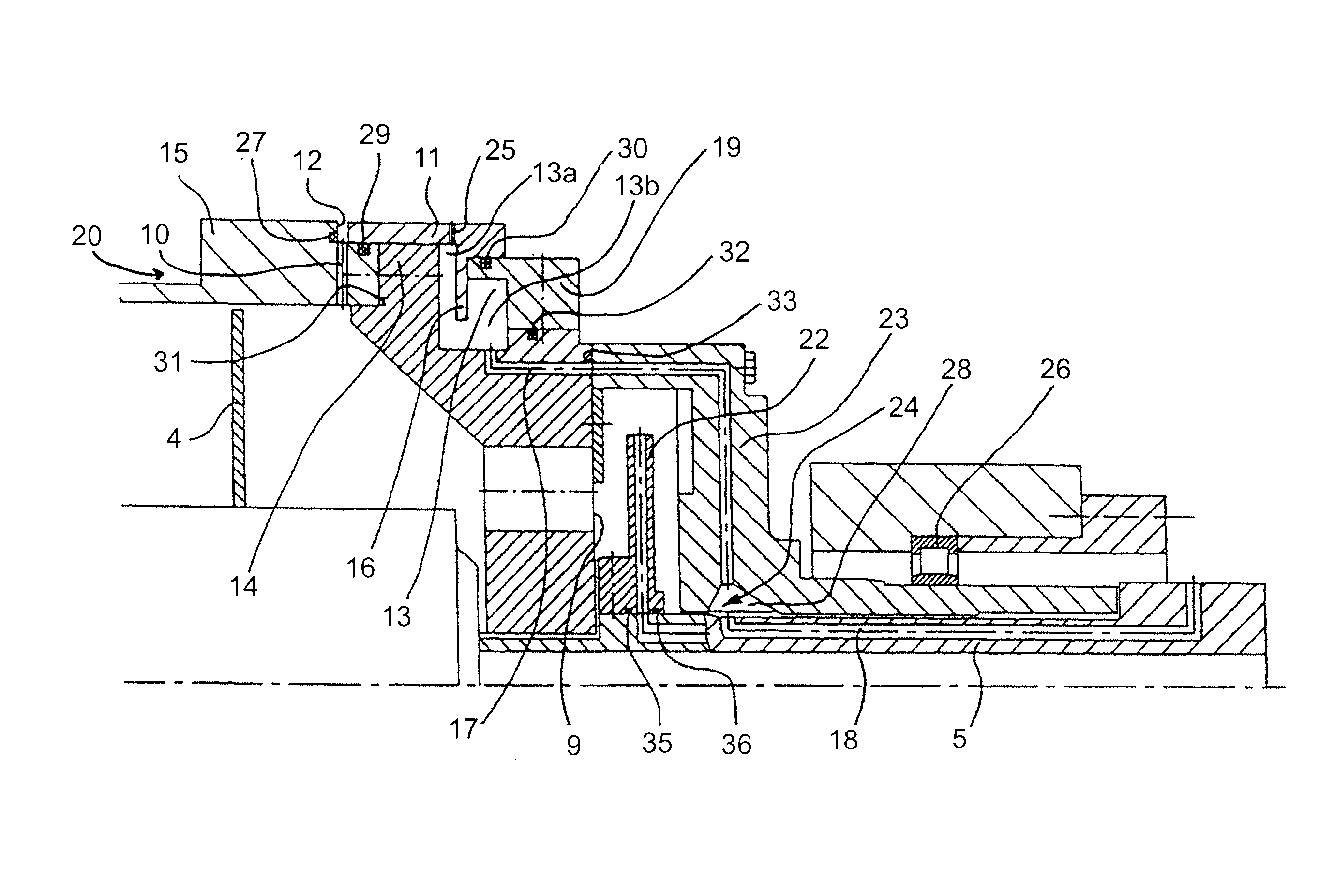
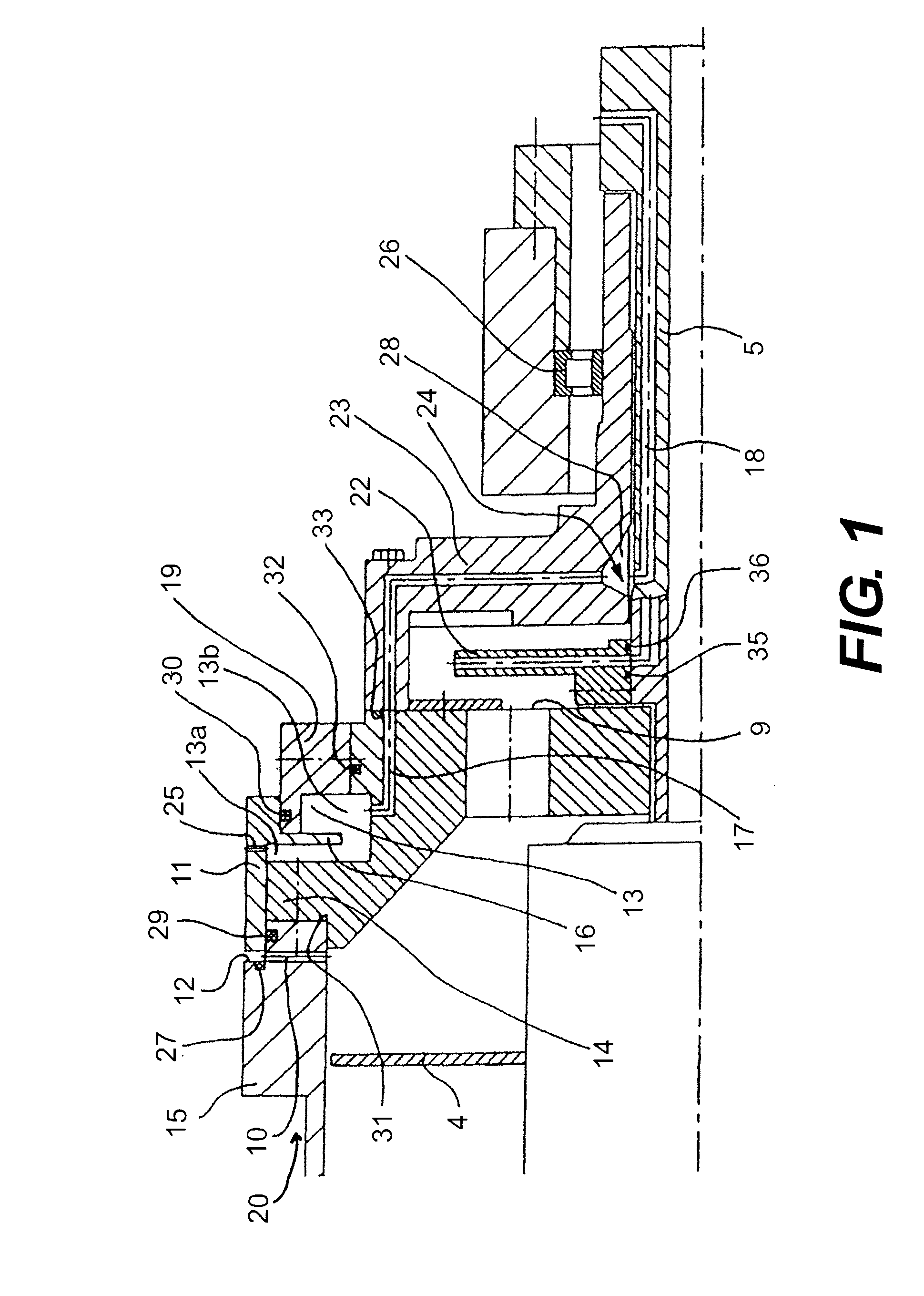
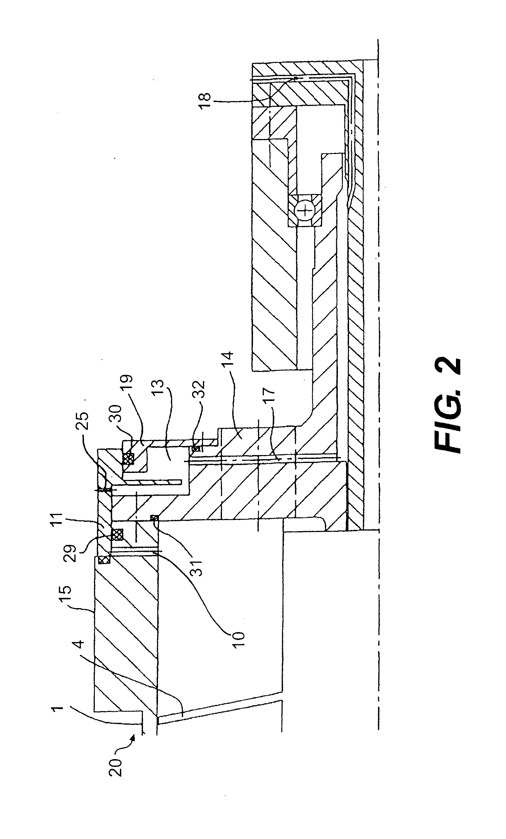
[0025]FIG. 5 shows a solid-bowl screw centrifuge having a drum 1 which can rotate about a horizontal axis of rotation and which has a cylindrical portion 2 and a tapering portion 3. A rotatable screw 4 is arranged in the drum 1. The centrifuge has a configuration and mode of operation such that the drum 1 and the screw 4 have a rotational speed difference, generally a relatively minor one, in operation. The drum bearing is designated by reference numeral 26.

[0026]The solid-bowl screw centrifuge of FIG. 1 is used to separate a product that is passed through a feed pipe 5 and a manifold 6 into the centrifuging space 7 in the drum 1. The product is separated into at least a solids phase and one or more liquid phases. On account of the density difference, the solids phase accumulates at the outside of the drum 1, from where it is carried by the screw 4 toward a solids discharge 8 at a tapering end of the drum 1 and is then continuously removed from the drum 1 through the solids discharg...


PUM


Abstract

A solid-bowl centrifuge that includes a drum rotatable about a horizontal axis of rotation and a screw arranged in the drum. Also included are a continuous solids discharge located at a first end of the drum and a continuous liquid discharge located at a second, opposite end of the drum. Further included is at least one discontinuously acting outlet opening including a closure device.

Description

CROSS-REFERENCE TO RELATED APPLICATIONS[0001]This application is a National Phase Application based upon and claiming the benefit of priority of PCT / EP2007 / 052697, filed on Mar. 21, 2007 and of German Application No. 10 2006 015 211.5, filed on Mar. 30, 2006 and of German Application No. 10 2006 030 477.2, filed on Jul. 1, 2006, the contents of these Applications being hereby incorporated herein by reference.BACKGROUND AND SUMMARY[0002]The present disclosure relates to a solid-bowl screw centrifuge including a drum rotatable about, for example, a horizontal axis of rotation. A rotatable screw is arranged in the drum. The centrifuge includes a continuous solid discharge at one end of the drum and a continuous liquids discharge at an opposite end of the drum. Further included is at least one discontinuously acting outlet opening having a closure device.[0003]A wide range of designs of solid-bowl screw centrifuges are known. As the drum slows down, the ring of liquid in the drum collap...

Claims


Application Information

Patent Timeline
Patent Type & Authority Patents(United States)
IPC IPC(8): B04B1/20B04B11/04
CPCB04B1/20B04B2001/2083
Inventor HORSTKOTTER, LUDGERBEYER, HANS-JOACHIMHORBACH, ULRICHDROSTE, JOHANNES
Owner GEA MECHANICAL EQUIP
Features
  • R&D
  • Intellectual Property
  • Life Sciences
  • Materials
  • Tech Scout
  • Unparalleled Data Quality
  • Higher Quality Content
  • 60% Fewer Hallucinations
Learn More