
Electroencephalogram interface system, electroencephalogram interface apparatus, method, and computer program

a technology of electroencephalogram and interface system, applied in the field of interface system, can solve problems such as inability to realize device manipulation, inability to input information intended by users, and difficulty in making inputs

Active Publication Date: 2013-06-18
PANASONIC CORP
View PDF15 Cites 16 Cited by
  • Summary
  • Abstract
  • Description
  • Claims
  • Application Information

AI Technical Summary

Benefits of technology

The present invention relates to an electroencephalogram interface apparatus, method, and computer program that can determine which parts of the interface a user is looking at and which part should be highlighted to catch the user's attention. This makes it easier for users to select the options they need without being inconvenienced or frustrated by the system. The technical effect of this invention is to improve the user experience and efficiency when using an electroencephalogram interface.

Problems solved by technology

However, when both hands are unavailable due to tasks other than device manipulations, e.g., household chores, rearing of children, and driving an automobile, it is difficult to make an input by using the manipulation inputting means, so that a device manipulation cannot be realized.
According to this technique, if a threshold value of the time for detecting an eyelid closure motion of the user is set to a small value, for example, even an unconsciously performed blink will be incorrectly detected as the selection of an option being finalized, thus leading to a possibility that an inputting of information not intended by the user may occur.
On the other hand, if the threshold value of the time for detecting an eyelid closure motion of the user is set to a large value, the possibility of incorrect detections related to blinks will be reduced, but the user will need to consciously maintain an eyelid closure motion for a long time, such that muscles around the eye may be fatigued due to too much strain.
Therefore, options cannot always be selected efficiently.
As a result, the following problems have occurred.
A first example is that, even if the coordinate position of an option which is displayed on an electroencephalogram interface is clear, the user cannot quickly select an option of interest.
This is a long time which would result in a feeling of inconvenience or frustration when a manipulation of a device to be used daily is contemplated.
A second example is that a user who is unclear and undecided as to what to select cannot smoothly make up his or her mind.
The reason is that, when a large number of options are highlighted to a user who is unclear as to what to select, such highlighting will be unnecessary and disturbing to the user.

Method used


Image

  • Electroencephalogram interface system, electroencephalogram interface apparatus, method, and computer program
  • Electroencephalogram interface system, electroencephalogram interface apparatus, method, and computer program
  • Electroencephalogram interface system, electroencephalogram interface apparatus, method, and computer program

Examples


embodiment 1

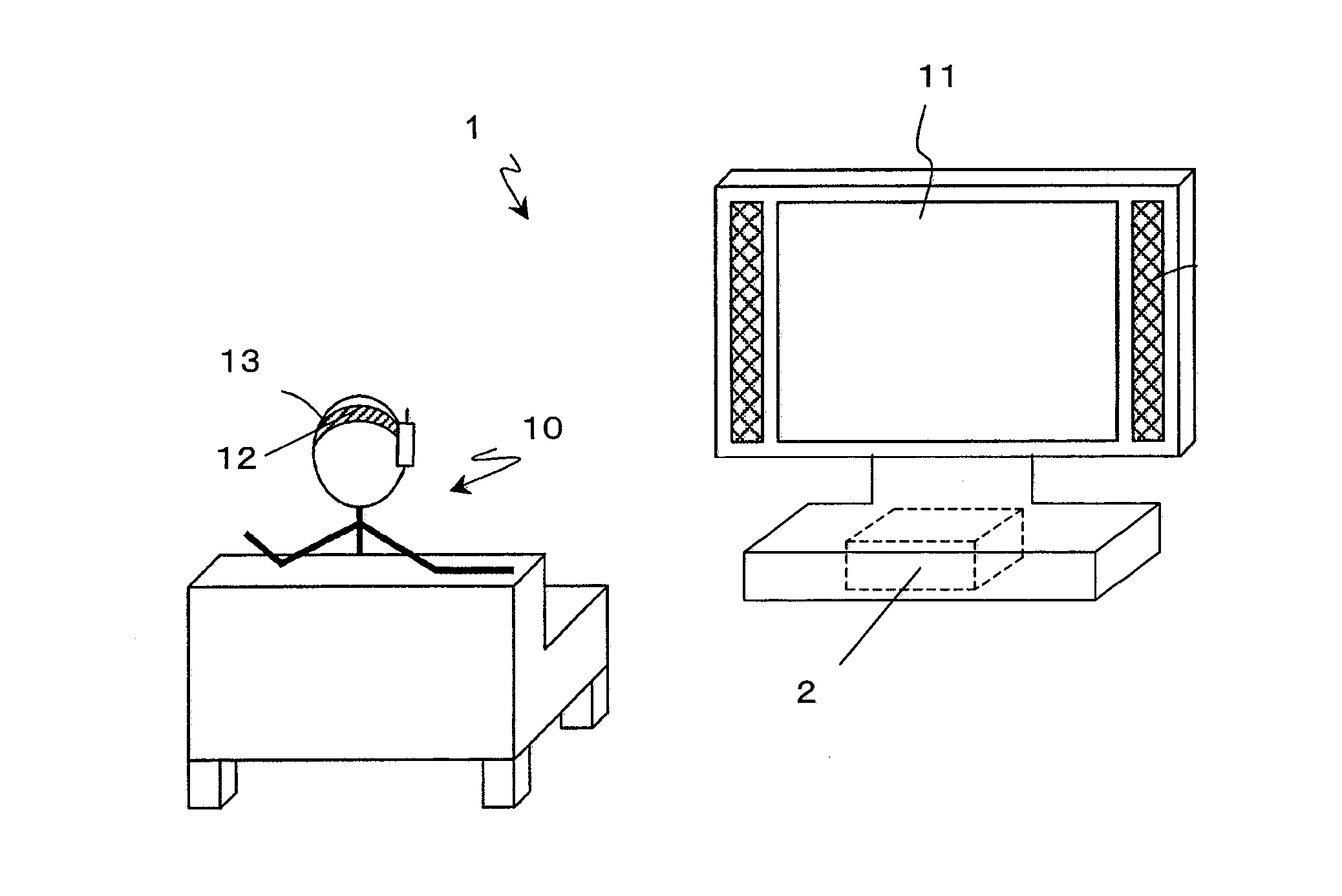
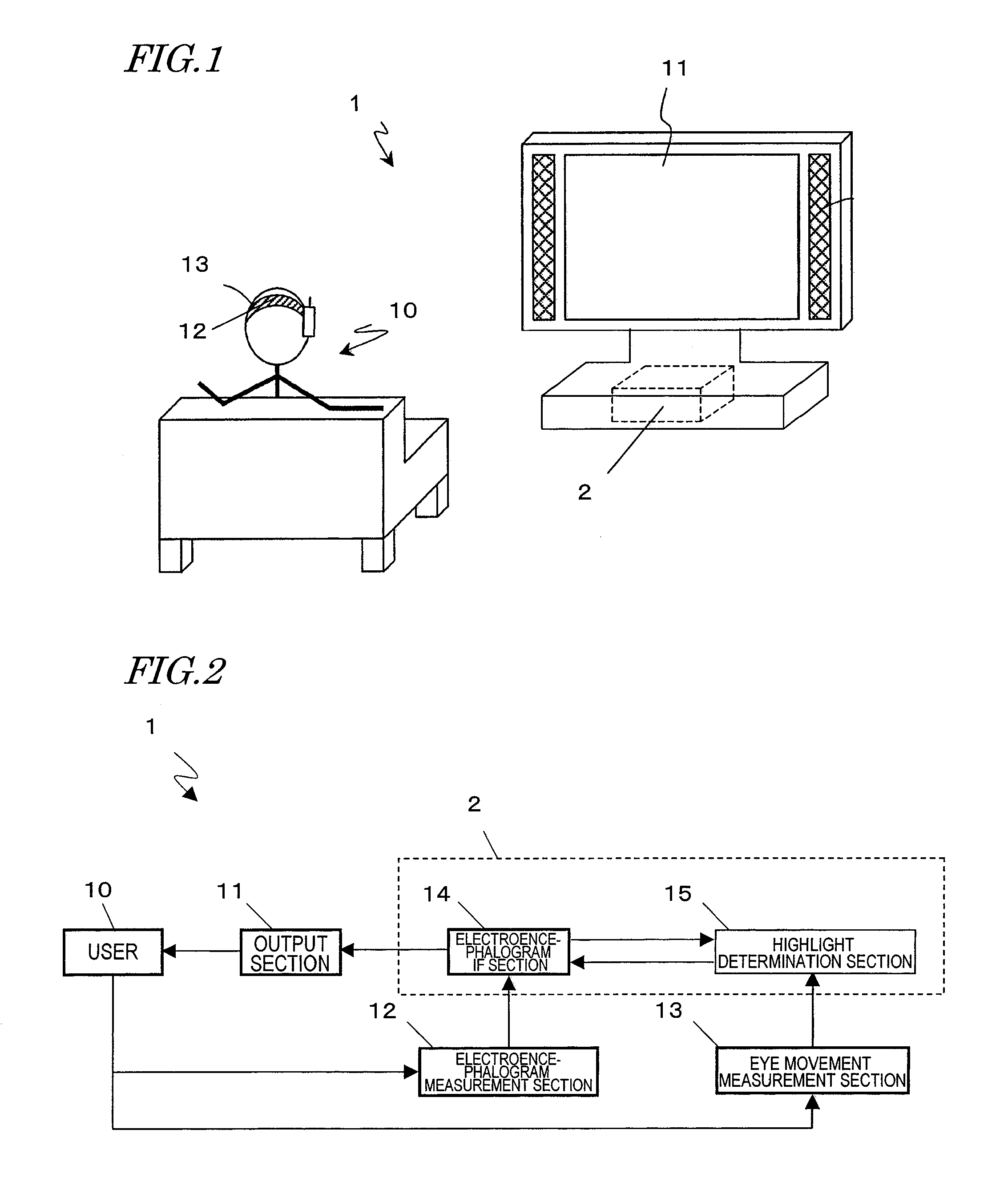
[0067]FIG. 2 shows a functional block construction of the electroencephalogram interface system 1 according to the present embodiment. The electroencephalogram interface system 1 includes an electroencephalogram interface apparatus 2, an output section 11, an electroencephalogram measurement section 12, and an eye movement measurement section 13. The electroencephalogram interface apparatus 2, which is composed of an electroencephalogram interface section (electroencephalogram IF section) 14 and a highlight determination section 15, is connected to each of the output section 11, the electroencephalogram measurement section 12, and the eye movement measurement section 13 in a wired or wireless manner, and performs transmission and reception of signals. The user 10 block is illustrated for convenience of explanation.

[0068]To the user 10, the output section 11 outputs a content, or a menu for selection in an electroencephalogram interface. Since the television set 11 shown in FIG. 1 is...

embodiment 2

[0139]In the electroencephalogram interface system 1 of Embodiment 1, concerning the highlighting which is required for an electroencephalogram interface, options to be highlighted and the timing of beginning the highlighting are determined based on the eye movement of the user 10. In Embodiment 1, the predetermined time from a point when the rotational angular velocity of an eyeball of the user 10 becomes equal to or less than a threshold value and until beginning the highlighting, and the time interval of highlighting, are constant values.

[0140]However, an ability to flexibly perform a more efficient selection according to the state of the user would be more preferable. Specifically, in the case where the user 10 knows the positions of options to be displayed on an electroencephalogram interface screen in advance, because of having used the electroencephalogram interface system 1 many times or for some other reasons, it would be more preferable to allow the user 10 to more quickly...


PUM


Abstract

An electroencephalogram interface system includes: sections for measuring an electroencephalogram and an eye movement; an output section for presenting on a screen an option related to a device operation; a highlight determination section for, if a predetermined time has elapsed since a rotational angular velocity of the eye movement becomes equal to or less than a threshold value, identifying a region of the screen in which the user is fixing one's gaze based on the eye movement, and determining an option to be highlighted; an interface section for highlighting the determined option, and determining an operation of the device based on an event-related potential in the signal based on the timing of highlighting the option; and a timing adjustment section for adjusting a timing of beginning highlighting based on the eye movement after a process of displaying the option on the screen is begun and until the option is displayed on the screen.

Description

[0001]This is a continuation of International Application No. PCT / JP2009 / 000172, with an international filing date of Jan. 20, 2009, which claims priority of Japanese Patent Application No. 2008-014901, filed on Jan. 25, 2008, the contents of which are hereby incorporated by reference.BACKGROUND OF THE INVENTION[0002]1. Field of the Invention[0003]The present invention relates to an interface (electroencephalogram interface) system with which it is possible to manipulate a device by utilizing an electroencephalogram. More specifically, the present invention relates to an electroencephalogram interface system having a function of efficiently selecting an option which is desired by a user, from among a large number of options.[0004]2. Description of the Related Art[0005]In recent years, various types of information devices such as television sets, mobile phones, and PDAs (Personal Digital Assistants) have become prevalent, and thus a user needs to manipulate information devices in man...

Claims


Application Information

Patent Timeline
Patent Type & Authority Patents(United States)
IPC IPC(8): G09G5/08G06F3/0346G06F3/038G06F3/048
CPCG06F3/013G06F3/015G06F2203/0381
Inventor NAKADA, TORUMORIKAWA, KOJI
Owner PANASONIC CORP
Learn More