Eureka AIR delivers breakthrough ideas for toughest innovation challenges, trusted by R&D personnel around the world.

Miniature micro-electromechanical system (MEMS) based directional sound sensor

a micro-electromechanical system and directional sound sensor technology, applied in the field of sound sensors, can solve the problems of large system and bulkyness

Active Publication Date: 2013-06-18
UNITED STATES OF AMERICA
View PDF3 Cites 14 Cited by
  • Summary
  • Abstract
  • Description
  • Claims
  • Application Information

AI Technical Summary

Benefits of technology

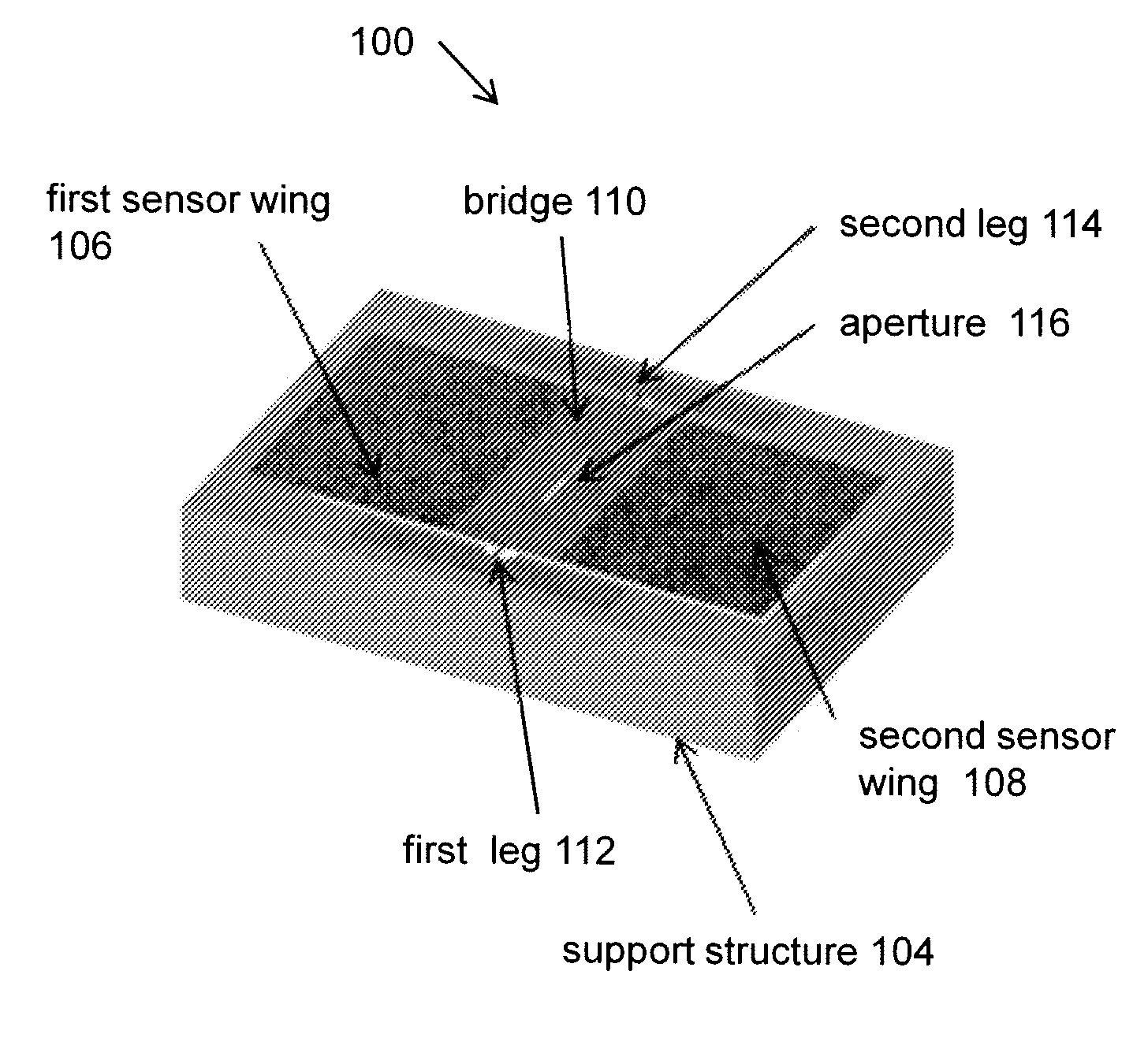
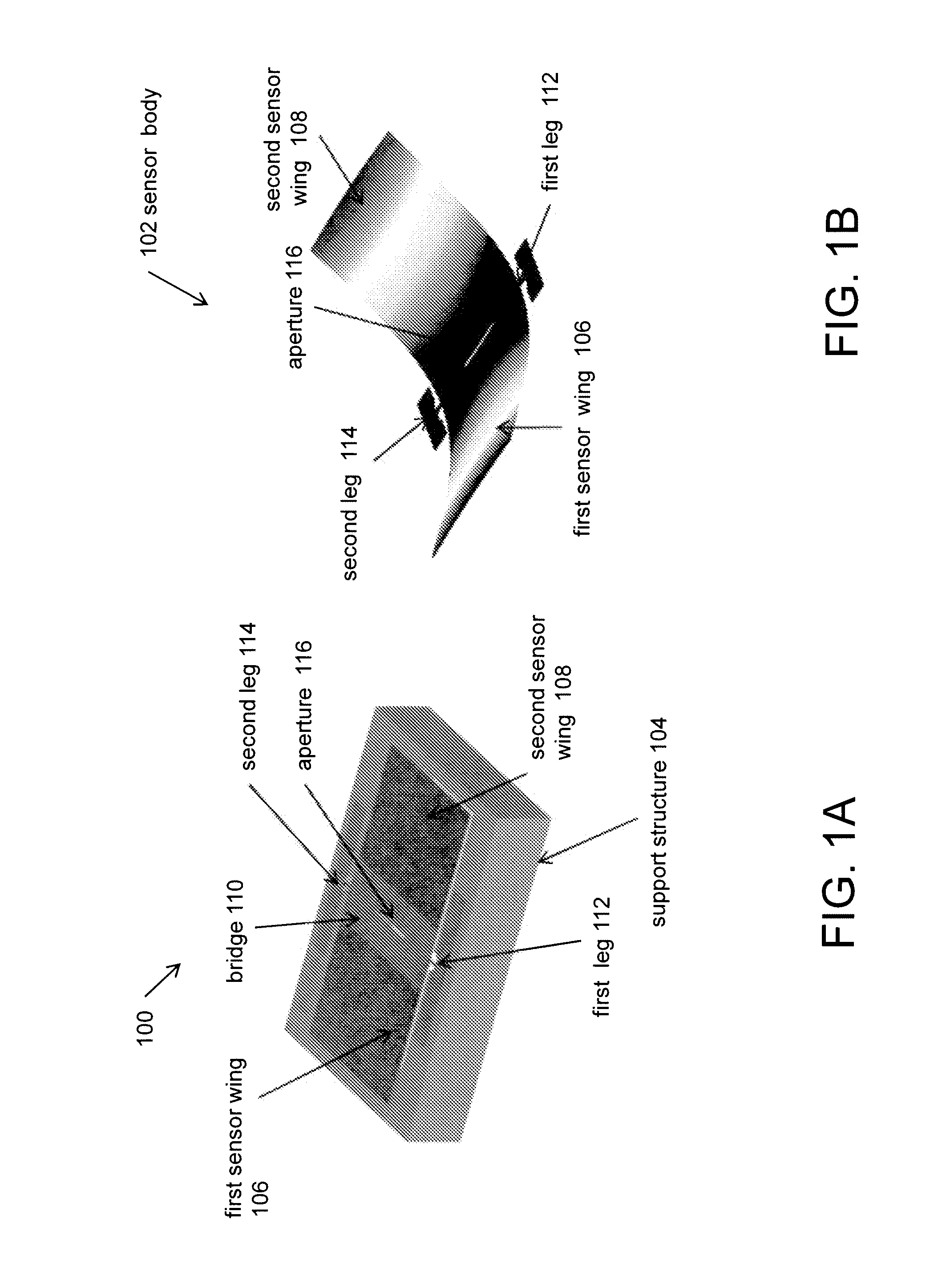
[0009]a second sensor wing; a bridge coupling the first sensor wing and the second sensor wing; a first leg connected to the bridge; and a second leg connected to the bridge; and a support structure, the support structure connected to the sensor body at the first leg and the second leg, wherein the support structure is hollow beneath the sensor body, allowing the sensor body to vibrate upon sound excitation. In one embodiment, interdigitated comb finger capacitors located at the edges of the first and second sensor wings enable an electrostatic (capacitive) readout that allows determination of the incident sound direction. In one embodiment, the use of at least two MEMS based directional sounds sensors oriented at different angles allows determination of the direction of sound in more than one plane.
[0010]In accordance with another embodiment, a method for making a micro-electromechanical system (MEMS) based directional sound sensor includes: obtaining a silicon on insulator (SOI) substrate; forming a sensor body from the SOI substrate, the sensor body including: a first sensor wing; a second sensor wing; a bridge coupling the first sensor wing and the second sensor wing; a first leg connected to the bridge; and a second leg connected to the bridge; and forming a support structure from the SOI substrate, wherein the support structure is connected to the sensor body at the first leg and the second leg, and further wherein the support structure is hollow beneath the sensor body allowing the sensor body to vibrate in response to sound excitation. In one embodiment, the sensor body and support structure include electrically conductive paths for communicating information related to the sound excitation of the sensor body to an external device, such as a microprocessor, for determination of the direction of sound. In one embodiment, interdigitated comb finger capacitors enable electrostatic (capacitive) readout associated with sound excitation of the first sensor and second sensor wings that allows determination of the incident sound direction.

Problems solved by technology

The accuracy of the directionality is determined by the extent of spatial separation of the microphones in the array making such a system relatively large and bulky.

Method used


Image

  • Miniature micro-electromechanical system (MEMS) based directional sound sensor
  • Miniature micro-electromechanical system (MEMS) based directional sound sensor
  • Miniature micro-electromechanical system (MEMS) based directional sound sensor

Examples


Embodiment Construction

[0025]Directional sound sensing systems generally use an array of omnidirectional microphones to sense the time and pressure difference between multiple locations. Given the sound speed, the direction of the sound source in relation to the array can be determined. In this type of configuration, the accuracy of the calculated direction is largely dependent on the extent of separation between array nodes. This requirement for spatial separation poses a significant challenge for fabricating systems which are much smaller than the wavelengths of interest because the responses at all locations are essentially in-phase and practically no measurable difference is observed between nodes. However, the Ormia Ochracea fly achieves the directional sound sensing by using ears that are separated by a mere 500 μm.

[0026]The separation of the ears of the fly is too small for it to sense the direction of a sound source, if it uses the difference in arrival times and amplitudes of sound at each ear, a...


PUM


Abstract

A micro-electromechanical (MEMS) based directional sound sensor includes a two sensor wings attached to a surrounding support structure by two legs. The support structure is hollow beneath the sensor wings allowing the sensor wings to vibrate in response to sound excitation. In one embodiment, interdigitated comb finger capacitors attached on the sensor wing edges and the support structure enable an electrostatic (capacitive) readout related to the vibrations of the sensor which allows determination of the sound direction.

Description

CROSS-REFERENCE TO RELATED APPLICATIONS[0001]This application claims the benefit of U.S. Provisional Application No. 61 / 167,466, filed Apr. 7, 2009, which is hereby incorporated in its entirety by reference.BACKGROUND OF THE INVENTION[0002]1. Field of the Invention[0003]The present invention relates generally to sound sensors.[0004]More particularly, the invention relates to a directional sound sensor.[0005]2. Description of the Related Art[0006]Currently, accurate determination of the direction of sound arrival requires an array of spatially separated microphones monitoring the arrival times and amplitudes of different microphones. The accuracy of the directionality is determined by the extent of spatial separation of the microphones in the array making such a system relatively large and bulky.SUMMARY OF THE INVENTION[0007]Embodiments in accordance with the invention provide a miniature micro-electromechanical system (MEMS) based directional sound sensor for uniquely determining th...

Claims


Application Information

Patent Timeline
Patent Type & Authority Patents(United States)
IPC IPC(8): H04R3/00H04R9/08H04R19/04H04R1/40
CPCH04R19/04H04R3/00H01L27/1203H04R1/406H04R3/005H04R9/08
Inventor KARUNASIRI, GAMANISINIBALDI, JOSE
Owner UNITED STATES OF AMERICA
Why Eureka
Eureka Blog
Learn More