Single control lever for combined control of the throttle of one or more engines and of a reversing gear mechanism

a technology of combined control and throttle, which is applied in the direction of gearing control, manual actuation control mechanism, propulsive elements, etc., can solve the problems of affecting the perfect synchronization of the throttle, the throttle control mechanism, and the build-up of mechanical tolerances, so as to achieve the effect of increasing the rpm

Inactive Publication Date: 2013-06-18
ULTRAFLEX
View PDF18 Cites 0 Cited by
  • Summary
  • Abstract
  • Description
  • Claims
  • Application Information

AI Technical Summary

Benefits of technology

[0019]For an angular travel of 30° from the center position either in the direction of the positive end position or of the negative end position, the rotation of the lever and its support shaft causes the main reversing gear keyed to said support shaft of the lever to move, thereby driving a mechanical reversing actuator and allowing switching from the neutral position to the forward or reverse gear.
[0020]For such entire 30° angular travel, the axial pin integral with the main reversing gear slides within the arched coupling slot without transferring any motion to the main transducer control gear, and allows the electromechanical transducers to remain in a state that corresponds to a minimum rpm engine throttle control condition. Instead, once the angular amplitude of rotation exceeds 30°, the axial coupling pin drives the main transducer control gear, and allows the angular motion of the lever through the electromechanical transducers to control the throttle of the engine / s and hence to cause their acceleration, i.e. to increase rpm.

Problems solved by technology

These configurations have the drawback that the engine throttle control mechanism does not completely uncouple from the lever for the angular reversing travel of said lever.
This situation may cause the buildup of mechanical tolerances in gears, which hinders perfect synchronization of the throttle control mechanism with the reversing gear mechanism.
Thus, the synchronization of the reversing gear mechanism with the engine throttle control mechanism may fail, causing problems for the proper operation of the engines and the reversing gear mechanism.
Those problems may lead, in the most serious cases, to damages of various degrees.

Method used


Image

  • Single control lever for combined control of the throttle of one or more engines and of a reversing gear mechanism
  • Single control lever for combined control of the throttle of one or more engines and of a reversing gear mechanism
  • Single control lever for combined control of the throttle of one or more engines and of a reversing gear mechanism

Examples


Embodiment Construction

[0050]Detailed descriptions of embodiments of the invention are provided herein. It is to be understood, however, that the present invention may be embodied in various forms. Therefore, the specific details disclosed herein are not to be interpreted as limiting, but rather as a representative basis for teaching one skilled in the art how to employ the present invention in different detailed systems, structures, or manners.

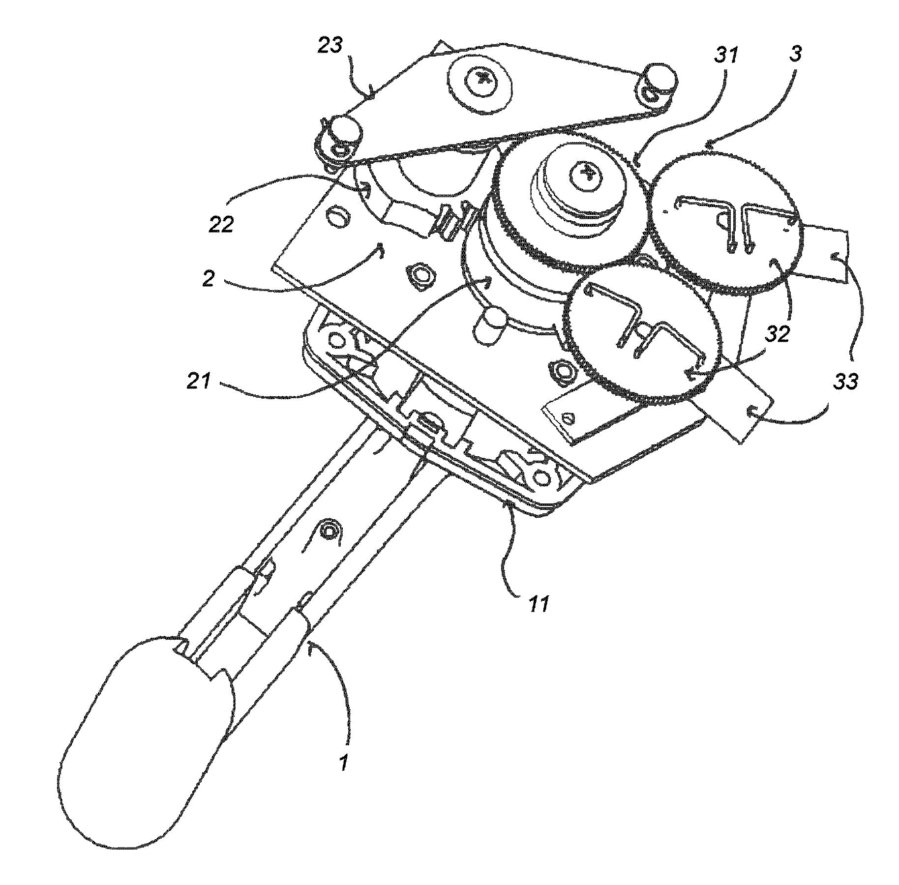
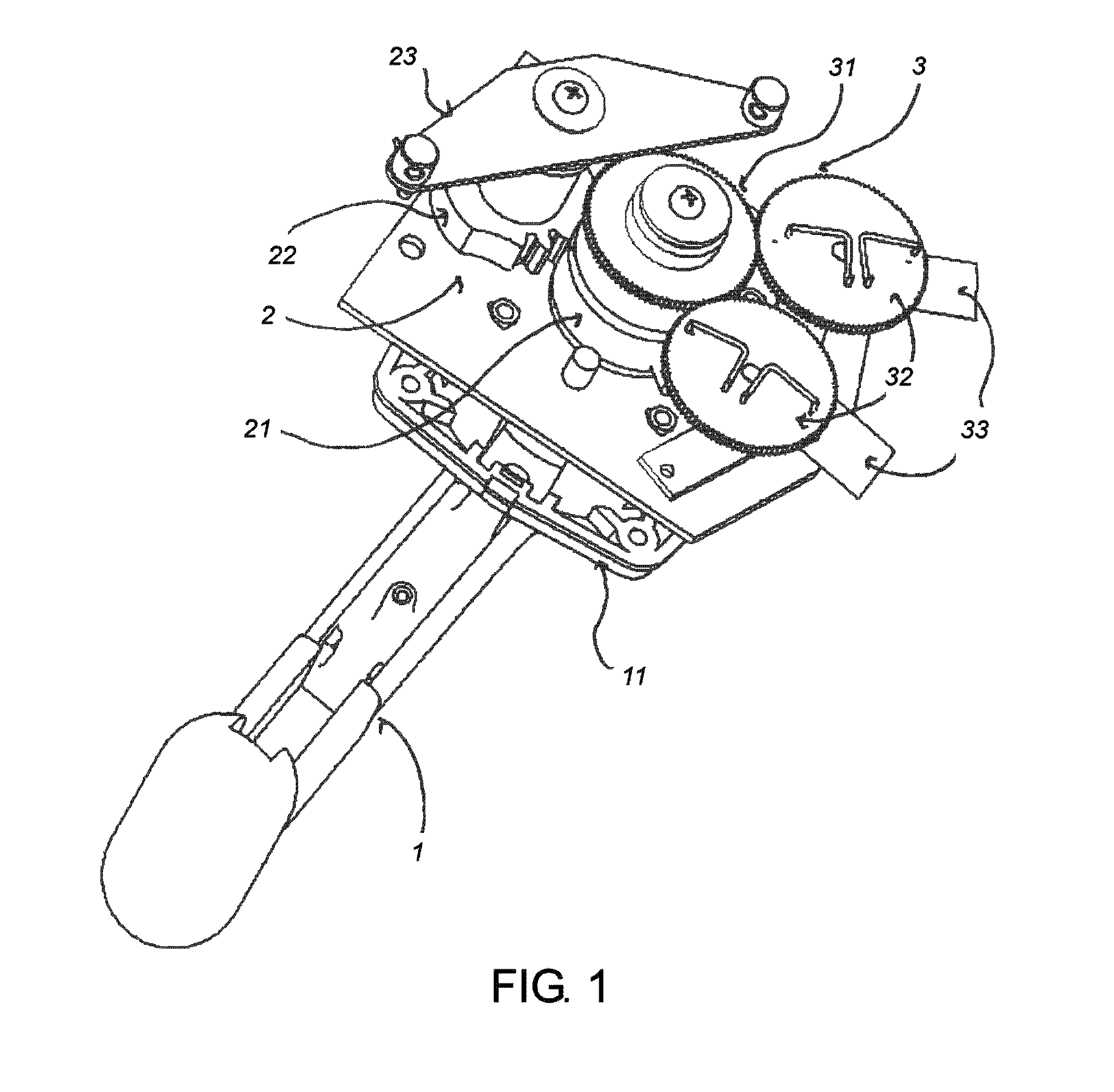
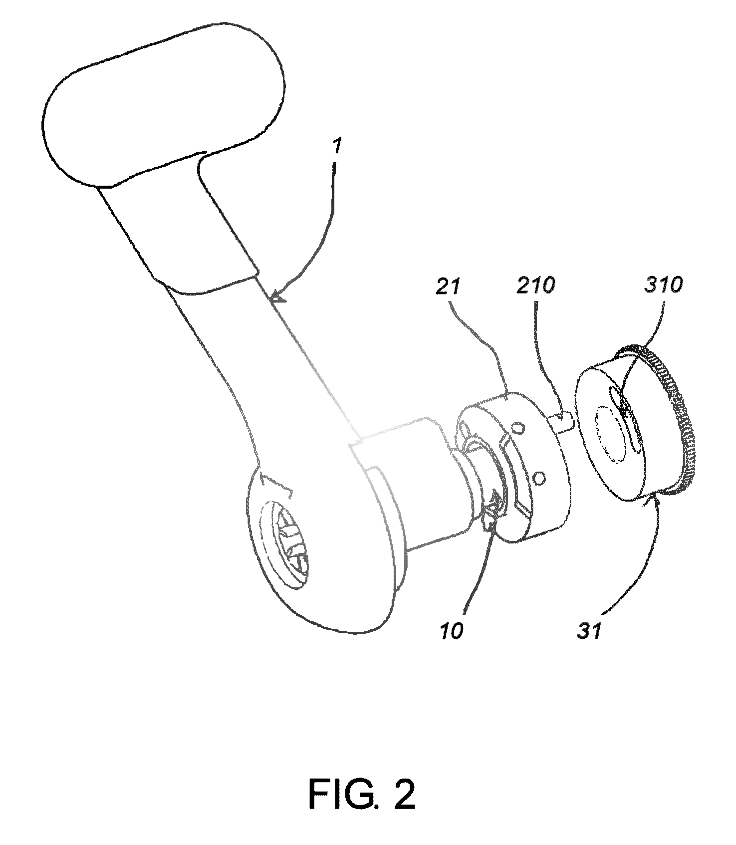
[0051]FIG. 1 illustrates a rear view of the lever 1, of the kinematic chain 2 that couples the lever support shaft (not shown) to the drive mechanism of a mechanical reversing actuator 23, and of the kinematic chain 3 that couples the lever support shaft to the electromechanical transducers 33.

[0052]The lever 1 is pivotally fixed to a plate 11, allowing fastening of the plate 11 to a wall (not shown), i.e. of a boat. The lever shaft passes through said plate and engages with the back of said wall, by the kinematic chains 2 and 3.

[0053]The kinematic chain 2 that cou...


PUM


Abstract

A single lever control for combined control of the throttle of one or more engines, for example of boats, and of a reversing gear mechanism includes a system that alternately couples and uncouples the motion of the lever to the reversing gear driving mechanism and to the members controlling the throttle of the one or more engines as a function of the angular position of the lever.

Description

FIELD OF THE INVENTION[0001]The present invention relates to a single lever control for the combined control of the throttle of one or more engines, for example for boats, and of a reversing gear mechanism.[0002]Said single lever includes a lever integrally mounted to a support shaft that oscillates about its longitudinal axis; a drive mechanism of a mechanical reversing actuator; and one or more electromechanical transducers.[0003]The angular travel of the oscillating lever identifies two end positions of an oscillation range, i.e. a positive end position and a negative end position, corresponding respectively to the forward gear at maximum rotations per minute (rpm) of the one or more engines and the reverse gear at maximum rpm of the engine / s, and also identifies an intermediate position between said two end positions, corresponding to the neutral state at minimum rpm of the engine / s.[0004]The angular motion of the lever and of said support shaft is converted by kinematic chains ...

Claims


Application Information

Patent Timeline
Patent Type & Authority Patents(United States)
IPC IPC(8): F02D9/00G05G9/00G05G13/00F16H59/02
CPCB60W10/06B60W10/10B60W30/18181B63H21/213F02D11/02G05G9/00B63H21/21B60Y2200/24B60Y2200/42Y10T74/20079Y10T74/20073
Inventor GAI, GIORGIOCAMPAGNA, MARCOVACCARI, MARCO
Owner ULTRAFLEX
Why Eureka
Try Eureka