Power generation unit and a method generating electric energy

a power generation unit and electric energy technology, applied in the direction of electric generator control, renewable energy generation, greenhouse gas reduction, etc., can solve the problems of mechanical measures being sources of failures, costly measures for controlling the speed of the turbine, etc., and achieve a simple and reliable way of regulating the dc level

Inactive Publication Date: 2011-09-01
VERTICAL WIND AB
View PDF7 Cites 1 Cited by
  • Summary
  • Abstract
  • Description
  • Claims
  • Application Information

AI Technical Summary

Benefits of technology

[0014]Thereby a simple and reliable way of regulating the DC-level is provided by components that normally will be present in the electric control m

Problems solved by technology

This creates problem when supplying the energy to a network since the generated energy only for a certain rpm will match the network, but at other speeds ther

Method used


Image

  • Power generation unit and a method generating electric energy
  • Power generation unit and a method generating electric energy
  • Power generation unit and a method generating electric energy

Examples


Embodiment Construction

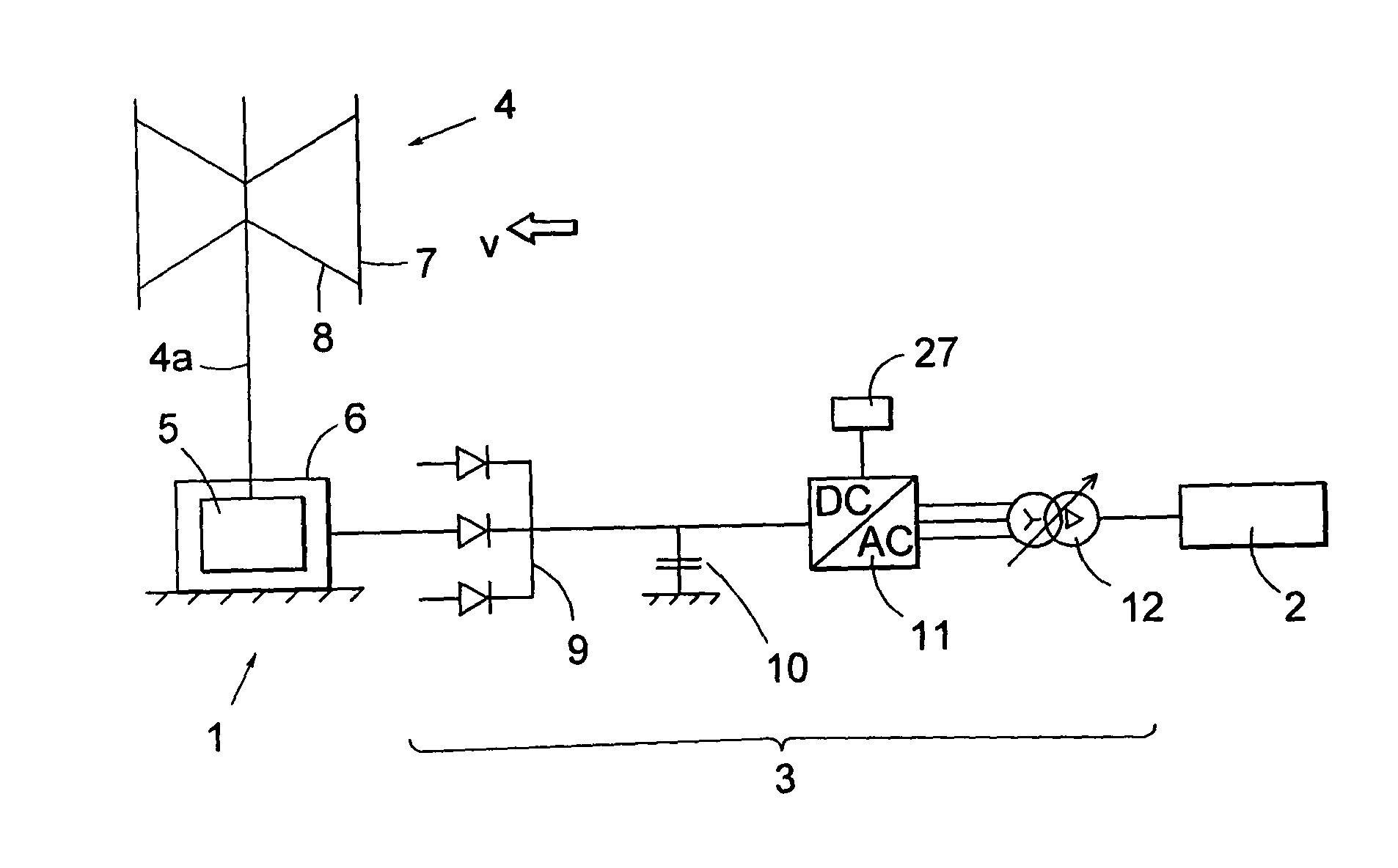
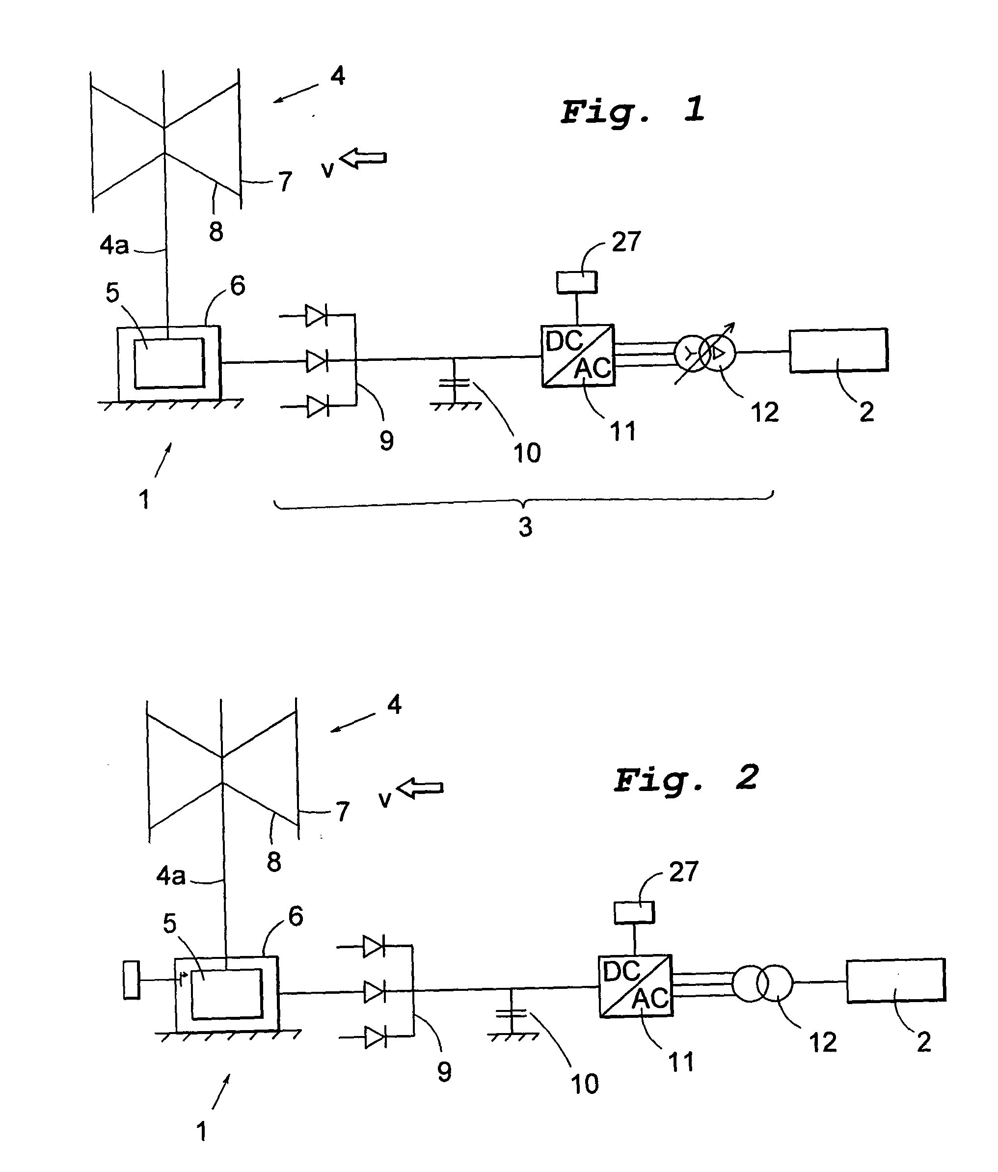
[0068]FIG. 1 schematically illustrates a wind power assembly 1 connected to a network 2. The wind power assembly has a vertical axis wind turbine 4 which is connected by a vertical shaft 4a to the rotor 5 of a generator 6. The turbine has a number of vertical blades 7, each blade 7 being connected to the shaft by a pair of arms 8. Typically the number of blades is three. The turbine is exposed to the wind having a velocity v.

[0069]The generator 6 is a synchronous generator and its rotor 5 is provided with permanent magnets. The voltage from the generator is supplied to a diode rectifier 9 such as to obtain DC. The DC-link is connected to ground via a capacitor 10. Thereafter an inverter supplies the voltage to the network through a transformer 12 with an output of e.g. 10 kV.

[0070]If the velocity v of the wind changes it affects the rpm of the turbine to be changed correspondingly. With the illustrated connection of the generator 5 to the network 2 and with a load angle about 10° th...


PUM


Abstract

The invention relates to a power generation unit. The unit has a turbine (3), a generator (8) and an electric connection means (9-12) connecting the generator (6) to an electric network (2). According to the invention the generator (8) is a permanent magnet synchronous generator, which has a low load angle. The electric connection means includes a diode rectifier (9) for supplying DC-voltage. The invention also relates to a use of the invented power generation unit and to a method for generating electric energy.

Description

FIELD OF INVENTION[0001]The present invention in a first aspect relates to a power generation unit including a turbine, a generator driven by the turbine, an electric connection means for connecting the generator to an electric network, and turbine speed control means.[0002]In a second aspect the invention relates to a use of such a power generation unit.[0003]In a third aspect the invention relates to a method for generating electric energy in which a turbine is exposed to a flowing fluid, the turbine drives a generator and the generator is connected to an electric network, and turbine speed control means.BACKGROUND OF THE INVENTION[0004]In most kinds of aggregates for generating electric energy the turbine is driven by a fast flowing fluid, e.g. water in a conventional hydropower plant or steam. The generator thereby is driven at substantially constant speed and the energy generated matches the network to which it is supplied.[0005]The continuously increasing demand for electric e...

Claims


Application Information

Patent Timeline
IPC IPC(8): H02P9/04
CPCF03D7/0272F03D7/06F03D9/003F05B2220/70642Y02E10/725F05B2240/214F05B2270/101H02P9/04H02P2101/15F05B2220/7068F03D9/255Y02E10/72Y02E10/74
Inventor LEIJON, MATSBERNHOFF, HANS
Owner VERTICAL WIND AB
Why Eureka
Try Eureka