Reinforced cross-laminated bulk container

a cross-laminated, bulk container technology, applied in the direction of containers, packaging, transportation and packaging, etc., can solve the problems of difficult fabrication and tab bendage, and achieve the effect of reducing the grad

Active Publication Date: 2013-06-25
INT PAPER CO
View PDF30 Cites 1 Cited by
  • Summary
  • Abstract
  • Description
  • Claims
  • Application Information

AI Technical Summary

Benefits of technology

[0009]The present invention solves the foregoing problems through a combination of features, including cross lamination of a corrugated inner liner and an outer component, double score profiles on the 180 degree folds, use of re-enforcing tape such as Sesame Tape or a comparable re-enforcing strand in the liner and in the outer component, with the reinforcing tape extending perpendicular to the respective corrugations in the liner and in the outer component, and pre-breaking of the scores in the liner before lamination with the outer component. The cross lamination of the inner liner and outer component, together with the cross-hatch pattern created by the direction of the reinforcing tape or strands, fortifies the sidewalls against bulge and permits use of lower grades of material in the cross corrugation liner.
[0010]In a preferred embodiment of the invention the container is sized so that four of them can fit on a single pallet. Although the structural limit to a container is governed by the machines used to produce the corrugated fibreboard and the laminator with which the components are joined, the smaller size containers are difficult to fabricate so that they can be shipped in a knocked down condition and easily erected by the user. Pre-breaking the scores of the cross laminated inner liner before it is laminated to the outer component provides ease of fabrication and makes it easier for the end-user to open up the container from a knocked down condition. By pre-breaking the scores deeper definition is given to the body scores and the surface tension is reduced when the panels are folded to form the container. In accordance with the invention, an inner jig is employed during the folding operation at the point of closing the glue joints on the container. The jig helps to form a more uniform geometry by forcing the 180 degree fold ends into two 90 degree pairs of double score features at the vertical corners of the container.
[0011]The resistance to folding of bulk containers, especially the smaller sizes that are in high demand, is of paramount concern, and has been one of the major weaknesses of previous designs. Resistance to folding is created by the small panel sizes and the laminated construction. To overcome this resistance in the present invention, the scores in the inner liner are pre-broken before the liner is laminated to the outer component, and double scores are placed at the point of the 180 degree folds. The double scores lessen the surface tension on the outermost facing, and each of the double scores, individually, only has to fold 90 degrees in the container of the invention, together forming the 180 degree fold.
[0012]In a preferred embodiment the container of the invention has an interlocking bottom flap construction that minimizes the risk of failure during handling, and avoids pinching of a bag liner when a bag is used. The interlocking bottom flaps are designed to provide trouble-free continuous performance during handling even when liquids are stored in the container. The interlocking bottom flaps include a pair of opposed intermediate or inner flaps that provide a full overlap on the inside of the container bottom, with a smooth surface to prevent pinching a bag liner and causing a leak when a bag is used inside the container. Both intermediate flaps have perf scores (also known as cut and crease) just past the points of overlap of the intermediate flaps to assist the user in moving the flaps to their operative positions by preventing binding on the outer flaps which interlock. The interlocking structure of the outer flaps comprises a narrowed tab on the end edge of one outer flap, and a shaped slot adjacent the end edge of the opposing outer flap. The tab has rounded corners to allow entry into the opposing slot, and the shape of the slot inhibits bending of the tab during use. The outer flap that contains the slot also has angled perf scores to facilitate bending of this flap down into the container far enough to permit the tab to be engaged in the slot during set-up. Once engaged, the two interlocked flaps are pulled back up to create a stable flat surface on which the container rests during use. The shaped slot incorporates an arc so that the slot has a generally chevron shape, rather than the typical linear or rectangular geometry that is commonly seen in similar interlocks. Conventionally shaped slots apply force in a straight line across the tab when excessive force is exerted against it from product inside the container, causing the tab to bend. The chevron shape of the slot of the invention helps prevent bending of the tab by dispersing the excessive pressures in a non-linear pattern.
[0016]The preferred embodiment of container according to the invention has interlocking flanges at its upper end, but it could be constructed with no flaps or flanges at its upper end, or partial flaps without interlocking characteristics, or a full flap closure with or without any overlap. The preferred embodiment comprises interlocking flanges such as shown in U.S. Pat. No. 6,076,730, the disclosure of which is incorporated in full herein by reference. Interlocking top flanges in combination with the other features described earlier aids in the needed sidewall rigidity, and in turn helps prevent bulging and ensures proper product containment. Proper containment is necessary for secure storage and transport, whether the product is a food or an industrial ingredient.
[0018]Further, a variety of flute configurations and combinations of the outer corrugated and the inner cross laminated corrugated could be used, such as singlewall (A-flute, B-flute, C-flute or any other flute size currently available) outer, and a cross laminated triplewall (AAA, ACA, CAA, CBA or any other flute combination currently available) inner. The inner cross corrugation could be any flute combination of doublewall and still provide adequate flexural rigidity which is needed for the practical use of the container.

Problems solved by technology

Although the structural limit to a container is governed by the machines used to produce the corrugated fibreboard and the laminator with which the components are joined, the smaller size containers are difficult to fabricate so that they can be shipped in a knocked down condition and easily erected by the user.
The resistance to folding of bulk containers, especially the smaller sizes that are in high demand, is of paramount concern, and has been one of the major weaknesses of previous designs.
Conventionally shaped slots apply force in a straight line across the tab when excessive force is exerted against it from product inside the container, causing the tab to bend.

Method used


Image

  • Reinforced cross-laminated bulk container
  • Reinforced cross-laminated bulk container
  • Reinforced cross-laminated bulk container

Examples


second embodiment

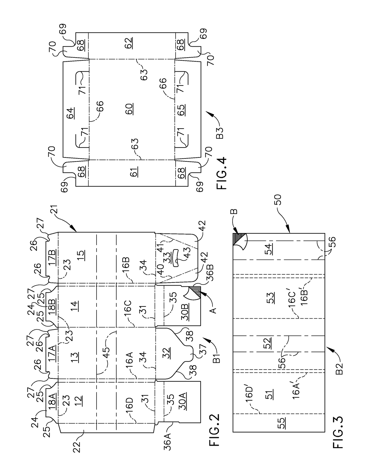
[0049]FIG. 7 is a top plan view of an alternative blank B4 for making the outer component of an alternative container 10′ according to the invention. The blank B4 comprises four sidewall panels 12′, 13′, 14′ and 15′ joined together along the respective scores 16A′, 16B′ and 16C′, with a glue flap 22′ foldably joined to one end edge of the blank B4 along the score 16D′ which effectively joins panel 12′ to panel 15′ when the container 10′ is constructed. The scores 16A′ and 16B′ are double scores as more fully described hereinafter and illustrated in applicant's prior U.S. Pat. No. 4,693,413, the disclosure of which is incorporated in full herein by reference. As described in that patent, the scores 16A′ and 16B′ extend along those corners joining sidewall panels that move through 180 degrees between the unfolded position of the blank B4 and the folded flat position of a container made from the blank.

[0050]In the second embodiment shown in FIG. 7, substantially identical bottom flaps ...

first embodiment

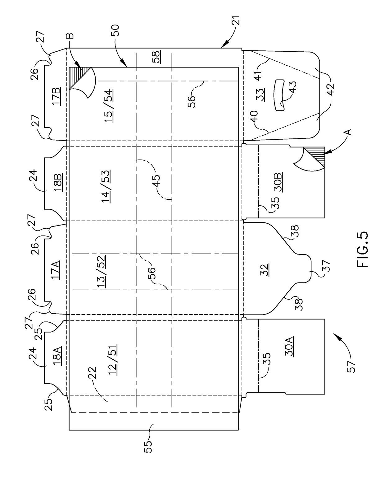
[0053]Similar to the first embodiment as shown in FIG. 2, a pair of reinforcing strands 45′ of Sesame Tape or other reinforcing strand known in the art extends across the blank B4 from one end edge to the other approximately midway between the top and bottom edges thereof. As indicated by the arrow “A” in FIG. 2, the corrugations of the outer component 21′ extend perpendicular to the top and bottom edges of the blank B4, and the reinforcing strands extend perpendicular to the corrugations.

[0054]FIG. 8 is a top plan view showing the inner liner 50 in FIG. 3 laminated to the outer component 21′ to form a laminated blank 57′ from which the container 10′ is erected according to the second embodiment of the invention. It will be noted that the liner 50 is shifted to the left as viewed in FIG. 8, with the glue flap 55′ on the liner projecting beyond the glue flap 22 on the outer component 21′, and the opposite end of the liner inset relative to the adjacent end of the outer component, def...

third embodiment

[0056]FIG. 10 is a top plan view showing the inner liner 50 in FIG. 3 laminated to the outer component 21″ preparatory to form a laminated blank 57″ from which the container 10″ is erected according to the invention. It will be noted that the liner 50 is shifted to the left as viewed in FIG. 10, with the glue flap 55″ on the liner projecting beyond the glue flap 22″ on the outer component 21″, and the opposite end of the liner inset relative to the adjacent end of the outer component, defining a space 58″ for attachment of the glue flap 55″. The Construction of the blank B5 including the inner liner 50 laminated thereto to form the container 10″ will be described hereinafter.

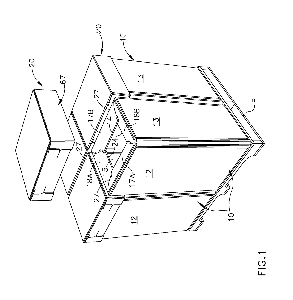
[0057]To set up a container 10′ and 10″ from its flattened condition to its expanded operative condition, it is opened into a tubular configuration and the partial top flaps are folded into their operative interlocked position as described previously herein. The container is then inverted so that it rests on its...


PUM


Abstract

A reinforced cross laminated corrugated paperboard bulk container has an outer component and an inner liner laminated to the outer component with the liner having corrugations extending perpendicular to the corrugations in the outer component. The bottom edges of the sidewalls include a first pair of flaps and a second pair of flaps each of which foldably extend outwardly therefrom and wherein each of the second pair of flaps having a pair of spaced apart triangularly shaped slots formed therein and wherein each of the first pair of flaps includes a pair of locking tabs formed on opposed end of the respective first pair of flaps which are engaged with the slots on the second pair of the flaps to securely close the bottom of the container. Vertical scores in the liner are pre-broken prior to laminating it to the outer component.

Description

CROSS REFERENCE TO RELATED APPLICATIONS[0001]This continuation-in part application claims priority to U.S. non-provisional patent application Ser. No. 12 / 755,887, filed on Apr. 4, 2010, which is hereby incorporated hereinto by reference as if fully restated herein.FIELD OF THE INVENTION[0002]This invention relates generally to bulk shipping and storage containers. More particularly, the invention relates to a bulk container made of reinforced cross-laminated corrugated paperboard. In a preferred embodiment the container has interlocking full bottom flaps and is especially adapted for containing fluid products.BACKGROUND OF THE INVENTION[0003]In the bulk handling of materials, and especially fluid or flowable materials such as liquids, powders and granules, containers of 20 to 80 gallon capacity are commonly used to transport and store the material. These containers should be capable of withstanding the weight of the contents and of being stacked on top of one another. They should al...

Claims


Application Information

Patent Timeline
Patent Type & Authority Patents(United States)
IPC IPC(8): B65D5/50
CPCB65D5/103B65D5/106B65D5/4266B65D5/445B65D5/566B65D19/20
Inventor TIMBROOK, RONALD D.MYERS, RYAN M.MOSS, WILLIAM F.PATRICKUS, MARTY
Owner INT PAPER CO
Why Eureka
Try Eureka