Method of piloting a multiple rotor rotary-wing drone to follow a curvilinear turn

a technology curvilinear turns, which is applied in the direction of remote control toys, navigation instruments, instruments, etc., can solve the problems of not being able to quickly pilot the drone, not being able to use the visual feedback on the screen of the appliance for piloting purposes, and requiring a certain amount of skill to achieve the effect of rotary wing drones

Inactive Publication Date: 2013-06-25
PARROT
View PDF19 Cites 91 Cited by
  • Summary
  • Abstract
  • Description
  • Claims
  • Application Information

AI Technical Summary

Benefits of technology

[0029]to reduce the number of degrees of freedom that the user needs to control in comparison with piloting with a combination of controls;
[0038]In a more complete version, the user is also given control over the speed at which the drone travels along this circular path, i.e. the user is given a second degree of freedom.
[0043]Very advantageously, the setpoint values generated in step c) control the horizontal linear speed and the inclination of the drone in such a manner as to maintain the drone at a zero radial speed relative to the circular path, so as to compensate for any side-slip or oversteer of the drone as it follows said path.

Problems solved by technology

These two types of movement (in XY translation and in pivoting) may be performed simultaneously, but doing so requires a certain amount of skill.
This first method of operation (with controls that are dissociated) does not enable the drone to be piloted quickly.
However under circumstances the front camera in the drone no longer points in the forward direction of the drone, and the visual feedback on the screen of the appliance cannot be used for piloting purposes.
In any event, even when piloting with simultaneous and combined controls, a fast tight turn gives rise to a non-negligible amount of centrifugal force that even an experienced user finds practically impossible to perceive and compensate once the speed exceeds a certain level, thus giving rise to a significant rise of side-slip or of oversteer of the drone with a consequence departure from the path of the race track.

Method used


Image

  • Method of piloting a multiple rotor rotary-wing drone to follow a curvilinear turn
  • Method of piloting a multiple rotor rotary-wing drone to follow a curvilinear turn
  • Method of piloting a multiple rotor rotary-wing drone to follow a curvilinear turn

Examples


Embodiment Construction

[0060]There follows a description of an implementation of the invention.

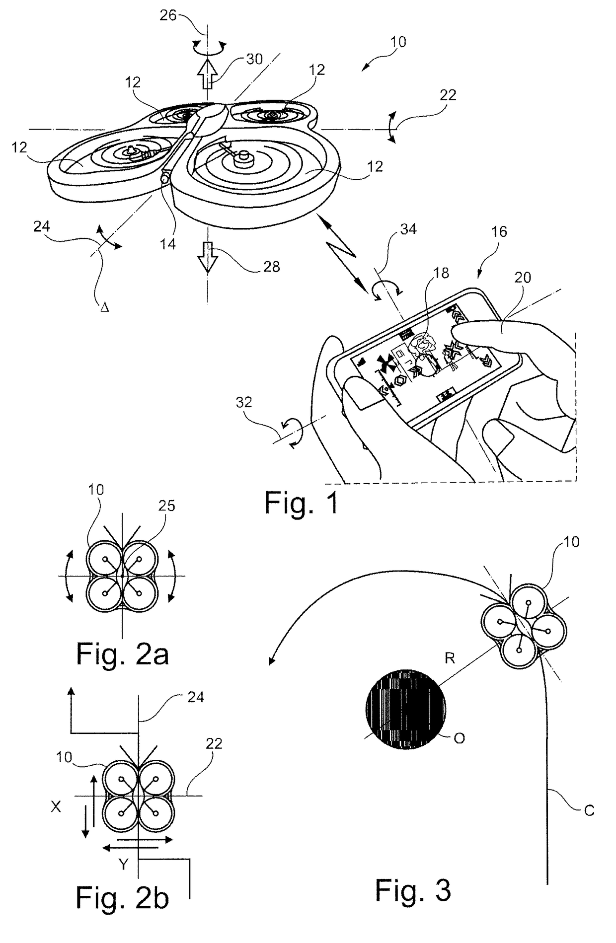
[0061]In FIG. 1, reference 10 is a general reference for a drone, which drone may for example be a quadricopter such as the model AR Drone from Parrot SA, Paris, France, as described in the above-mentioned WO 2010 / 061099 A2 and also in WO 2009 / 109711 A2 (which describes an example of an automatic stabilizer system operating on the basis of information supplied by an altimeter and a forward-looking camera) and FR 2 915 565 A1 (which describes in particular a gyro and accelerometer control system used by the drone).

[0062]The drone 10 has four coplanar rotors 12 driven by motors that are controlled independently by an integrated navigation and attitude control system. It is provided with a forward-looking, first camera 14 for obtaining an image of the scene towards which the drone is heading, e.g. a wide-angle CMOS sensor camera of VGA resolution (640×480 pixels) with a video stream refresh frequency of 15 frames p...


PUM


Abstract

The respective motors of the drone (10) can be controlled to rotate at different speeds in order to pilot the drone both in attitude and speed. A remote control appliance produces a command to turn along a curvilinear path, this command comprising a left or right turning direction parameter and a parameter that defines the radius of curvature of the turn. The drone receives said command and acquires instantaneous measurements of linear velocity components, of angles of inclination, and of angular speeds of the drone. On the basis of the received command and the acquired measurements, setpoint values are generated for a control loop for controlling motors of the drone, these setpoint values controlling horizontal linear speed and inclination of the drone relative to a frame of reference associated with the ground so as to cause the drone to follow curvilinear path (C) at predetermined tangential speed (u).

Description

FIELD OF THE INVENTION[0001]The invention relates to piloting rotary wing drones such as quadricopters or the like.[0002]Such drones are provided with multiple rotors driven by respective motors that can be controlled to rotate at different speeds in order to pilot the drone both in attitude and in speed.[0003]A typical example of such a drone is the AR. Drone from Parrot SA, Paris, France, which is a quadricopter fitted with a series of sensors (three-axis gyros, accelerometers, and altimeter). The drone is also provided with a front camera picking up an image of the scene to which the drone is directed, and a vertically-directed camera picking up an image of the terrain being overflown.[0004]The drone is piloted by a user making use of a remote control device that is separate from the drone,—referred to below as an “appliance”—and that is connected to the drone via a radio link.BACKGROUND OF THE INVENTION[0005]WO 2010 / 061099 A2 (Parrot SA) describes in particular one such drone an...

Claims


Application Information

Patent Timeline
Patent Type & Authority Patents(United States)
IPC IPC(8): G06F13/00
CPCA63H27/12A63H30/04G05D1/0202G08C17/02B64C2201/027B64C2201/042B64C2201/088G08C2201/93B64C2201/127B64C2201/146B64C2203/00B64C2201/108B64U10/13B64U2101/30B64U2201/20B64U30/20B64U50/19B64U70/80
Inventor RISCHMULLER, MICHAELD'HAEYER, FREDERIC
Owner PARROT
Why Eureka
Try Eureka