Monitoring of distributed power harvesting systems using DC power sources

a technology of distributed dc power sources and power harvesting systems, applied in the integration of power network operation systems, nuclear elements, electric devices, etc., can solve the problems of power loss, affecting the performance of solar arrays, and difficult to verify the correct operation of systems, so as to avoid or minimize collisions

Active Publication Date: 2013-06-25
SOLAREDGE TECH LTD
View PDF407 Cites 178 Cited by
  • Summary
  • Abstract
  • Description
  • Claims
  • Application Information

AI Technical Summary

Problems solved by technology

Conversely, a serial connection may fail to provide the required current, so that several strings of serial connections may need to be connected in parallel to provide the required current.
For example, various inconsistencies in manufacturing may cause two identical sources to provide different output characteristics.
Changes in temperature, solar irradiance and shading, either from near objects such as trees or far objects such as clouds, can cause power losses.
Owners and even professional installers find it difficult to verify the correct operation of the system.
With time, many more factors, such as aging, dust and dirt collection and module degradation affect the performance of the solar array.
Data collected at the inverter 104 is not sufficient to provide proper monitoring of the operation of the system.
However, a duplex transmission method requires additional transmission lines and complicates the system.
On the other hand, one-way transmission is prone to collisions and makes it difficult to compare data transmitted from the various sources.
Due to the wide variability of power output of such systems, and the wide range of environmental conditions that affect the power output, the output parameters from the overall system are not sufficient to verify whether the solar array is operating at peak power production.
Local disturbances, such as faulty installation, improper maintenance, reliability issues and obstructions might cause locals power losses which are difficult to detect from overall monitoring parameters.

Method used


Image

  • Monitoring of distributed power harvesting systems using DC power sources
  • Monitoring of distributed power harvesting systems using DC power sources
  • Monitoring of distributed power harvesting systems using DC power sources

Examples


Embodiment Construction

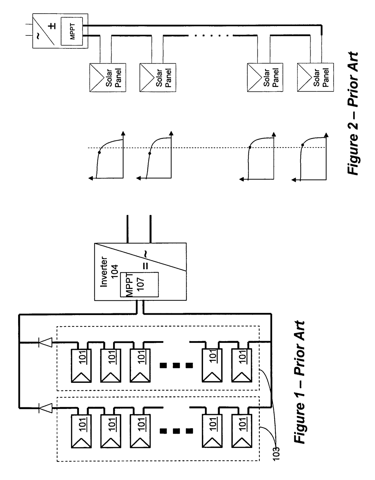
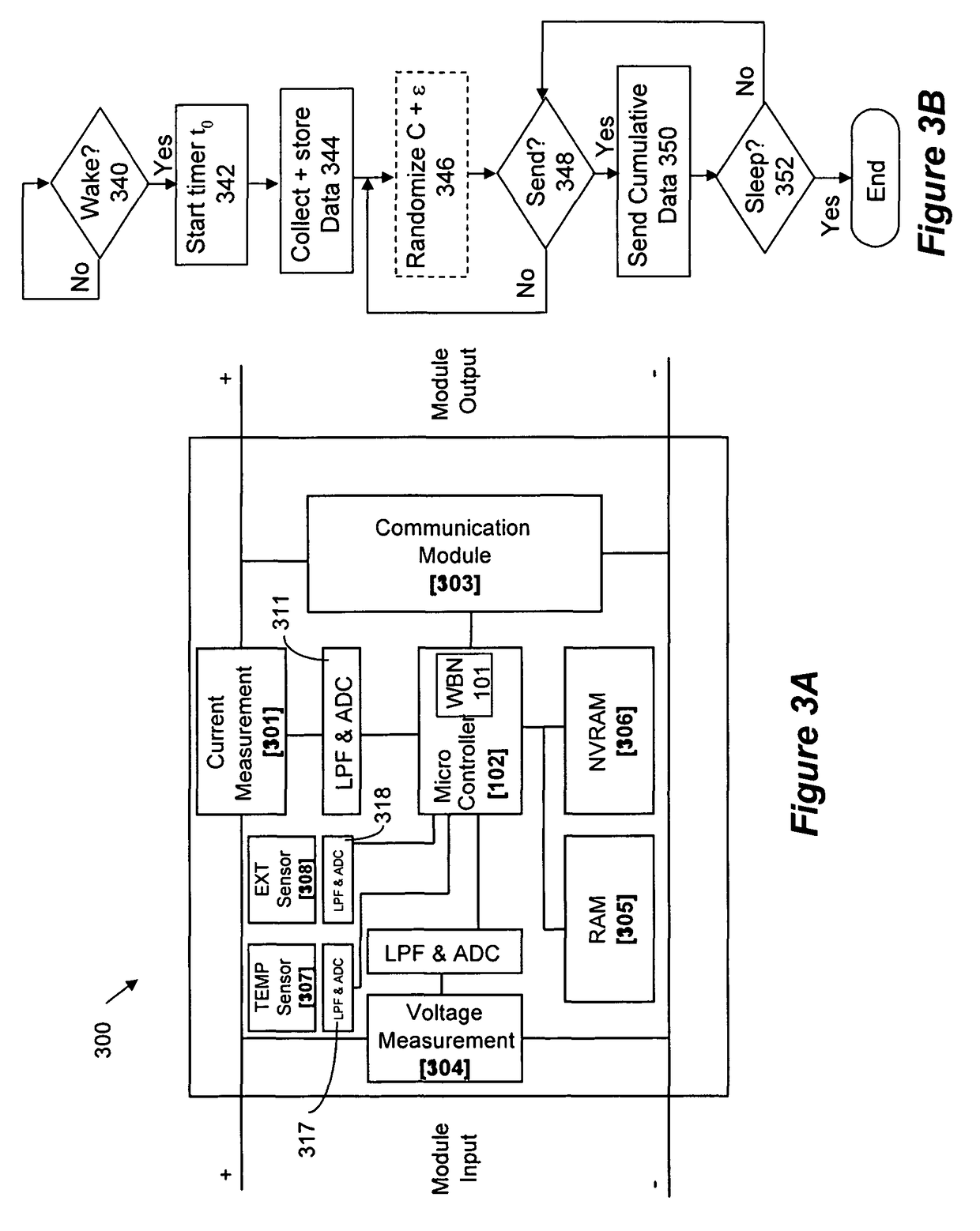
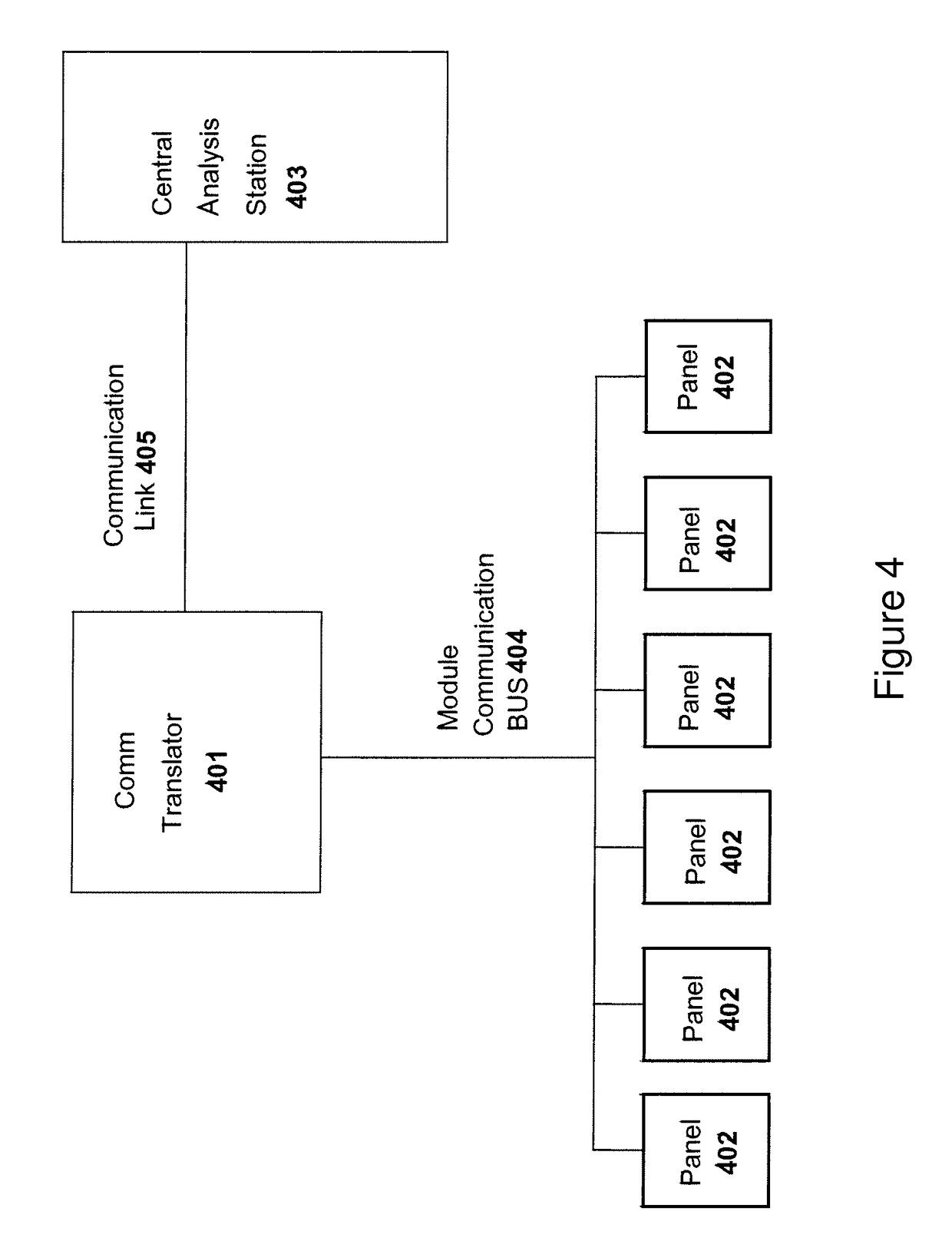
[0043]Aspects of the present invention provide a monitoring system for solar panel system. The monitoring system includes modules that may be attached to each solar panel of the solar system. The monitoring module will monitor several parameters including, etc., panel voltage, panel current, panel temperature, lighting conditions, spatial orientation (e.g., tilt), and other parameters. The information from each monitoring module may be transmitted to a central management unit together with a unique module ID. The transmission may be done over the powerlines, in wireless form, or with dedicated wiring—such as Ethernet, RS-232, RS-485 or other. In one aspect of the invention, transmission is done as power line communication in a one-way implementation. Collisions are avoided or minimized by using a unique transmission timing mechanism.

[0044]The central management unit may analyze the data from all solar panels. The monitoring system can be implemented at the string level, at the panel...


PUM


Abstract

A monitoring system and method for monitoring performance of individual powers sources in a distributed power source system. A monitoring module is coupled to each of the power sources, or to each string of serially connected power sources, to monitor and collect data regarding current, voltage, temperature and other environmental factors at the power source. The collected data is transmitted over a power line to a central analysis station for analysis. Data collected from each source indicates malfunction or degradation at the source. Comparison of data collected from adjacent sources filters for environmental factors impacting neighboring sources such as cloudy days for a solar panel. Comparison of data collected from the same source at different times indicates soiling or degradation of the source with time or periodic events such as a moving shade from an adjacent building.

Description

CROSS-REFERENCE TO RELATED APPLICATIONS[0001]This application claims priority to U.S. Provisional Patent Applications, Ser. No. 60 / 868,851, filed Dec. 6, 2006, and titled “Distributed Solar Array Monitoring, Management and Maintenance,” Ser. No. 60 / 868,893, filed Dec. 6, 2006, and titled “Distributed Power Harvesting System for Distributed Power Sources,” 60 / 868,962, filed Dec. 7, 2006, and titled “System, Method and Apparatus for Chemically Independent Battery,” Ser. No. 60 / 908,095, filed Mar. 26, 2007, and titled “System and Method for Power Harvesting from Distributed Power Sources,” and Ser. No. 60 / 916,815, filed May 9, 2007, and titled “Harvesting Power From Direct Current Power Sources,” the entire content of which is incorporated herein by reference. Further, this Application is related to ordinary U.S. patent application Ser. No. 11 / 950,224, filed Dec. 4, 2007, titled “Current Bypass for Distributed Power Harvesting Systems Using DC Power Sources,” patent application Ser. No...

Claims


Application Information

Patent Timeline
Patent Type & Authority Patents(United States)
IPC IPC(8): G06F15/00
CPCG01D4/004H02J3/385Y02E60/74Y02B70/343Y02B90/242Y02B90/245Y02B90/248Y04S20/322Y04S20/34Y04S20/40Y04S20/52Y02B70/346Y04S20/525H02J3/383Y02E10/563Y02B10/14Y02E40/72H02J13/0024H02J13/0062H02J13/0075Y02B90/2623Y02B90/2653Y02B90/2638Y02E10/58Y04S10/123Y04S10/30Y04S40/122Y04S40/124Y04S40/126Y02B70/3208H02J13/00009H02J13/00002H02J2300/26H02J3/381H02J13/00016H02J13/00026Y02B10/10Y02B70/34Y02B90/20Y02E10/56Y02E40/70Y02E60/00Y04S20/30Y04S40/121G01D2204/125G01D2204/30G01D2204/14G01D2204/35Y02E10/50Y02B70/30H02J13/00022H02J3/38H02J13/00G01R22/063G01R21/133
Inventor ADEST, MEIRHANDELSMAN, LIORGALIN, YOAVFISHELOV, AMIRSELLA, GUY
Owner SOLAREDGE TECH LTD
Why Eureka
Try Eureka