Glass manufacturing apparatuses with particulate removal devices and methods of using the same

a technology of glass manufacturing apparatus and particulate removal device, which is applied in the direction of glass rolling apparatus, manufacturing tools, press and blow machine, etc., can solve the problems of introducing defects into glass substrates, affecting consumer perception of the electronic device in which glass substrates are employed, and reducing the occurrence of onclusion defects. , the effect of reducing the occurrence of onclusion defects

Inactive Publication Date: 2013-07-16
CORNING INC
View PDF12 Cites 7 Cited by
  • Summary
  • Abstract
  • Description
  • Claims
  • Application Information

AI Technical Summary

Benefits of technology

[0007]The embodiments disclosed herein relate to fusion draw machines which mitigate the occurrence of onclusion defects on glass substrates caused by particulate matter. Also described herein are glass manufacturing apparatuses which incorporate such fusion draw machines as well as methods for drawing glass webs with reduced onclusion defects caused by particulate matter in a glass manufacturing apparatus.
[0009]According to another embodiment, a glass manufacturing apparatus which reduces the occurrences of onclusion defects caused by particulate matter is disclosed. The glass manufacturing apparatus includes a melting vessel for melting glass batch materials to form molten glass. A fining vessel for receiving the molten glass from the melting vessel and removing removing bubbles from the molten glass. A fusion draw machine receives the molten glass from the fining vessel, wherein the fusion draw machine comprises an enclosure and a forming vessel forming the molten glass into a glass web. A pull roll assembly is positioned in an interior of the enclosure and receives the glass web and draws the glass web in a downward draw direction. The glass manufacturing apparatus also includes a particulate removal device for removing particulate matter from the interior of the enclosure. The particulate removal device generally includes a vacuum nozzle positioned in the interior of the enclosure and fluidly coupled to a vacuum source. The vacuum source draws a vacuum through the vacuum nozzle to exhaust particulate matter and exhaust gas from the interior of the enclosure. A particulate filter is fluidly coupled to the vacuum nozzle and the vacuum source such that the particulate filter traps particulate matter exhausted from the interior of the enclosure through the vacuum nozzle. A cooling jacket is positioned around a vacuum line fluidly coupling the vacuum nozzle to the enclosure. The cooling jacket cools the exhaust gas exhausted from the interior of the enclosure.

Problems solved by technology

For example, defects and / or flaws present in the glass substrates may interfere with the optical properties of the glass substrates and, as a result, may degrade the performance of the electronic devices in which the glass substrates are employed.
Moreover, defects and / or flaws in glass substrates which are visually discernable may adversely impact consumer perception of the electronic device in which the glass substrates are employed.
In some instances, defects are introduced into the glass substrates after the glass has been formed into a substrate from molten glass batch materials.
For instance, particulate matter that becomes embedded in the surface of the glass substrate as the glass substrate is drawn during manufacture creates defects commonly called onclusions.
The onclusions cannot be readily washed off or removed from the glass substrate and, as such, glass substrates with onclusions are discarded as scrap as a quality control measure which decreases production efficiencies and increases production costs.

Method used


Image

  • Glass manufacturing apparatuses with particulate removal devices and methods of using the same
  • Glass manufacturing apparatuses with particulate removal devices and methods of using the same
  • Glass manufacturing apparatuses with particulate removal devices and methods of using the same

Examples


Embodiment Construction

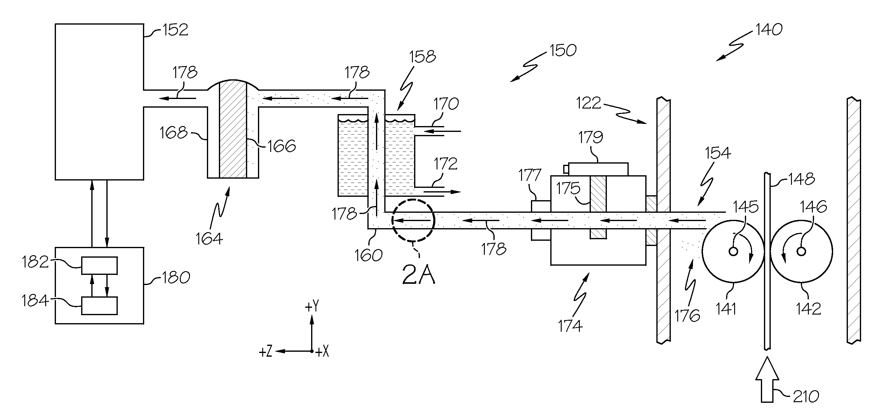
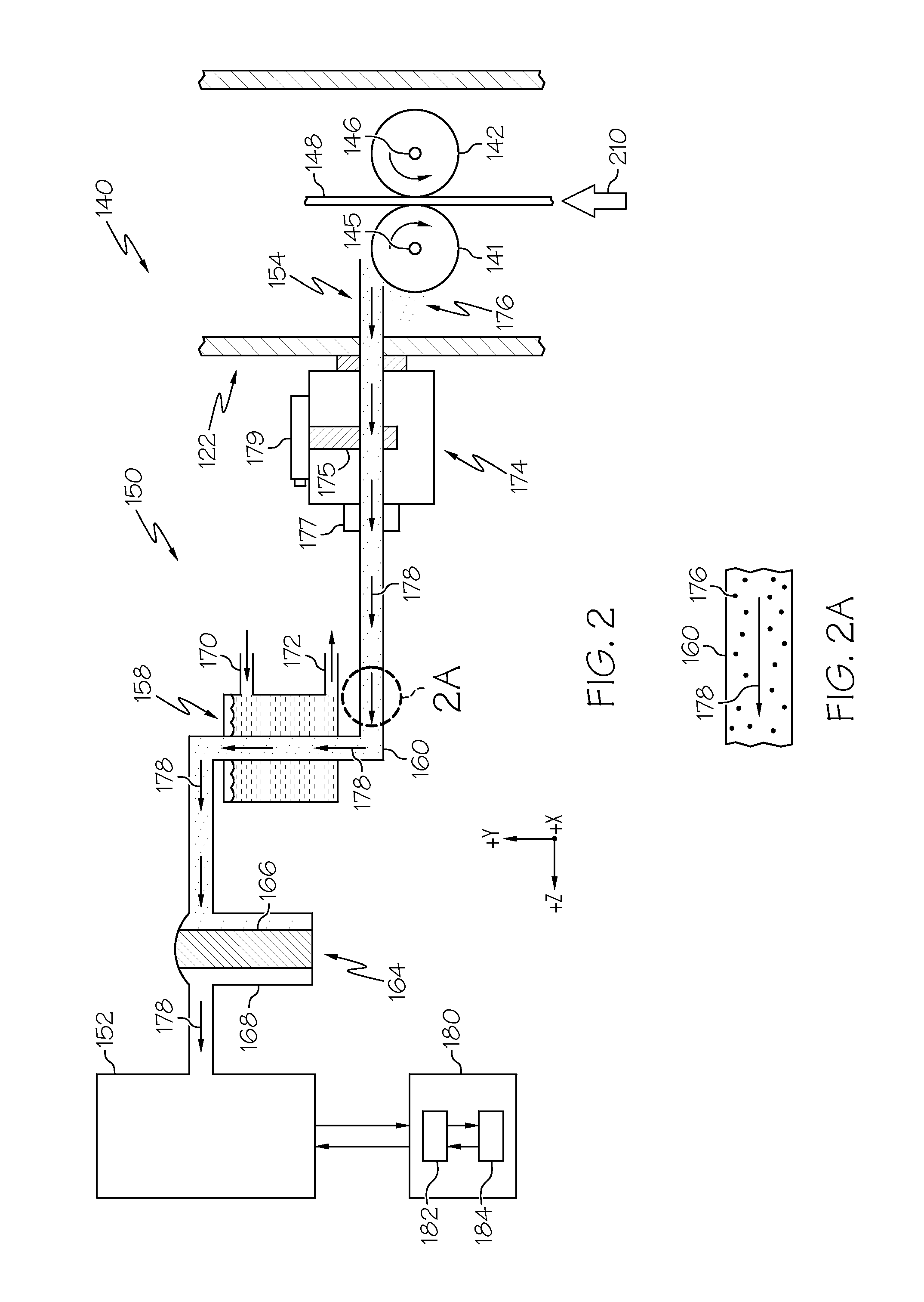
[0020]Reference will now be made in detail to various embodiments of fusion draw machines with particulate removal devices and glass manufacturing apparatuses utilizing the same, examples of which are illustrated in the accompanying drawings. Whenever possible, the same reference numerals will be used throughout the drawings to refer to the same or like parts. One embodiment of a portion of a fusion draw machine with a particulate removal device is schematically depicted in FIG. 2. The fusion draw machine includes an enclosure in which a pull roll assembly having a first pull roll and a second pull roll is rotatably positioned. A vacuum nozzle of the particulate removal device is positioned in the enclosure. The vacuum nozzle is connected to a particulate filter and a vacuum source such that a vacuum may be drawn through the vacuum nozzle. The fusion draw machine with the particulate removal device and methods for using the fusion draw machine in a glass manufacturing apparatus to r...


PUM

PropertyMeasurementUnit
emissivityaaaaaaaaaa
temperatureaaaaaaaaaa
temperaturesaaaaaaaaaa

Abstract

Glass manufacturing apparatuses with particulate removal devices and methods for using the same are disclosed. In one embodiment, a fusion draw machine for forming a glass web from molten glass includes an enclosure and a first pull roll and a second pull roll rotatably positioned in an interior of an enclosure. The first pull roll and the second pull roll cooperate to draw a glass web in a draw direction. A particulate removal device for removing particulate matter from the interior of the enclosure is fluidly coupled to the enclosure and includes a vacuum nozzle disposed in the interior of the enclosure and fluidly coupled to a vacuum source with a vacuum line. A particulate filter is fluidly coupled to the vacuum nozzle and the vacuum source and traps particulate matter exhausted from the interior of the enclosure through the vacuum nozzle.

Description

BACKGROUND[0001]1. Field[0002]The present specification generally relates to glass manufacturing apparatuses and, more specifically, to fusion draw machines with particulate removal devices and glass manufacturing apparatuses incorporating the same.[0003]2. Technical Background[0004]Glass substrates are commonly utilized in a variety of consumer electronic devices including smart phones, lap-top computers, LCD displays and similar electronic devices. The quality of the glass substrates used in such devices is important for both the functionality of such devices as well as the aesthetics of such devices. For example, defects and / or flaws present in the glass substrates may interfere with the optical properties of the glass substrates and, as a result, may degrade the performance of the electronic devices in which the glass substrates are employed. Moreover, defects and / or flaws in glass substrates which are visually discernable may adversely impact consumer perception of the electron...

Claims


Application Information

Patent Timeline
Patent Type & Authority Patents(United States)
IPC IPC(8): C03B17/06
CPCC03B17/068C03B17/064Y02P40/57C03B5/225C03B5/23C03B17/06
Inventor DELIA, ROBERTKAHLOUT, AHDI EL
Owner CORNING INC
Why Eureka
Try Eureka