Echo suppressing method and apparatus

a technology of applied in the field of echo suppression method and apparatus, can solve the problems of high echo removal amount, difficult to originate a call in the far-end side, etc., and achieve the effect of suppressing echo and small errors

Active Publication Date: 2013-07-16
NEC CORP
View PDF12 Cites 0 Cited by
  • Summary
  • Abstract
  • Description
  • Claims
  • Application Information

AI Technical Summary

Benefits of technology

[0021]As explained above, the present invention makes it possible to suppress the echo in an environment in which the near-end noise exists also when a situation of the distortion is changed. The reason is as follows.
[0022]When this echo canceller is a linear echo canceller, a harmonic wave component contained in the far-end signal almost directly appears in the output of the echo canceller. Further, the output of the echo canceller contains quite a few harmonic wave components contained in the far-end signal even when this echo canceller is a non-linear echo canceller. On the other hand, the near-end signal, being an input signal of the sound pickup apparatus, contains the echo of the far-end signal caused by the acoustic system coupling between the sound pickup apparatus and the loudspeaker, and the harmonic wave component generated by the non-linear component in addition to the near-end sound. This ratio of the harmonic wave components, namely, the value of a degree of the echo crosstalk due to the non-linear component becomes a value of a constant range as far as the limited purpose such as a voice call is concerned. The minimum value, out of the value of a constant range, is hardly influenced by the near-end sound and the near-end noise. Thus, using the value obtained by multiplying this minimum value or the value equivalent to the minimum value by a correction constant as a crosstalk coefficient and estimating an amount of the echo being contained in the first signal from the crosstalk coefficient and the second signal to subtract it from the first signal, or estimating a ratio of the near-end signal being contained in the first signal from the crosstalk coefficient and the first and second signals to multiply the first signal by this estimated ratio makes it possible to remove the non-linear component of the echo from the first signal. In such a manner, the error is made small even when the estimation is performed in an environment in which the near-end noise exists because the value equivalent to the minimum value is less influenced by the near-end noise, and as a result, the echo of which the distortion generated in the echo path is large can be sufficiently suppressed also in an environment in which the noise being contained in the near-end signal is large.

Problems solved by technology

When the far-end sound leaks at a high volume level, the delayed far-end sound is audible as an echo to a call partner, so that it becomes difficult to originate a call in the far-end side.
As a result, a high echo removal amount is gained.

Method used


Image

  • Echo suppressing method and apparatus
  • Echo suppressing method and apparatus
  • Echo suppressing method and apparatus

Examples


first example

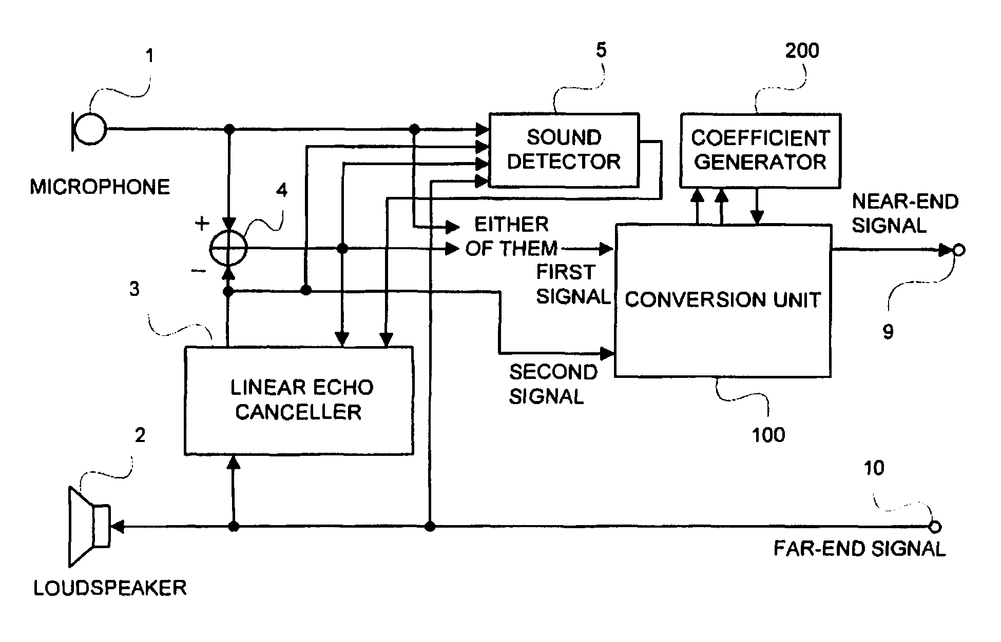
[0126]FIG. 13 is a block diagram of the first example of the present invention. A difference with the technology shown in FIG. 30 is that the coefficient generator 200 is mounted, a spectral subtraction unit 6 is inserted between the subtracter 4 and the output terminal 9 of the near-end signal of FIG. 30, and the above spectral subtraction unit 6 receives the output signal of the linear echo canceller 3, and yet receives the crosstalk coefficient being outputted by the coefficient generator 200.

[0127]The coefficient generator 200 generates the coefficient indicative of a degree of the echo crosstalk. The spectral subtraction unit 6 develops the output signal of the subtracter 4 and the output signal of the linear echo canceller 3 into respective frequency domains, and removes the echo frequency by frequency. Hereinafter, exemplary configurations and operations of the coefficient generator 200 and the spectral subtraction unit 6 will be explained in its order.

[0128]200>

[0129]The coe...

second example

[0158]FIG. 16 is a block diagram of the second example of the present invention. A difference with the first example shown in FIG. 13 is that while, as a signal being inputted into the spectral subtraction unit 6, the output of the subtracter 4 is employed in the first example, the output signal of the microphone 1 is employed in the second example. While the main component of the echo has been removed by the linear echo canceller 3 in the output of the subtracter 4, the echo has not been removed in the output signal of the microphone 1. This difference is a difference as to whether the removal of the main component of the echo is performed by the linear echo canceller 3 and the subtracter 4 or by the spectral subtraction unit 6, and the second example is completely identical to the first example in an advantageous effect for the distortion. Thus, also in the second example, the suppression of the echo can be suppressed at a high volume level also in the case that the echo cannot be...

third example

[0163]Next, an example employing a spectral suppression unit as the conversion unit 100 of FIG. 1 will be explained.

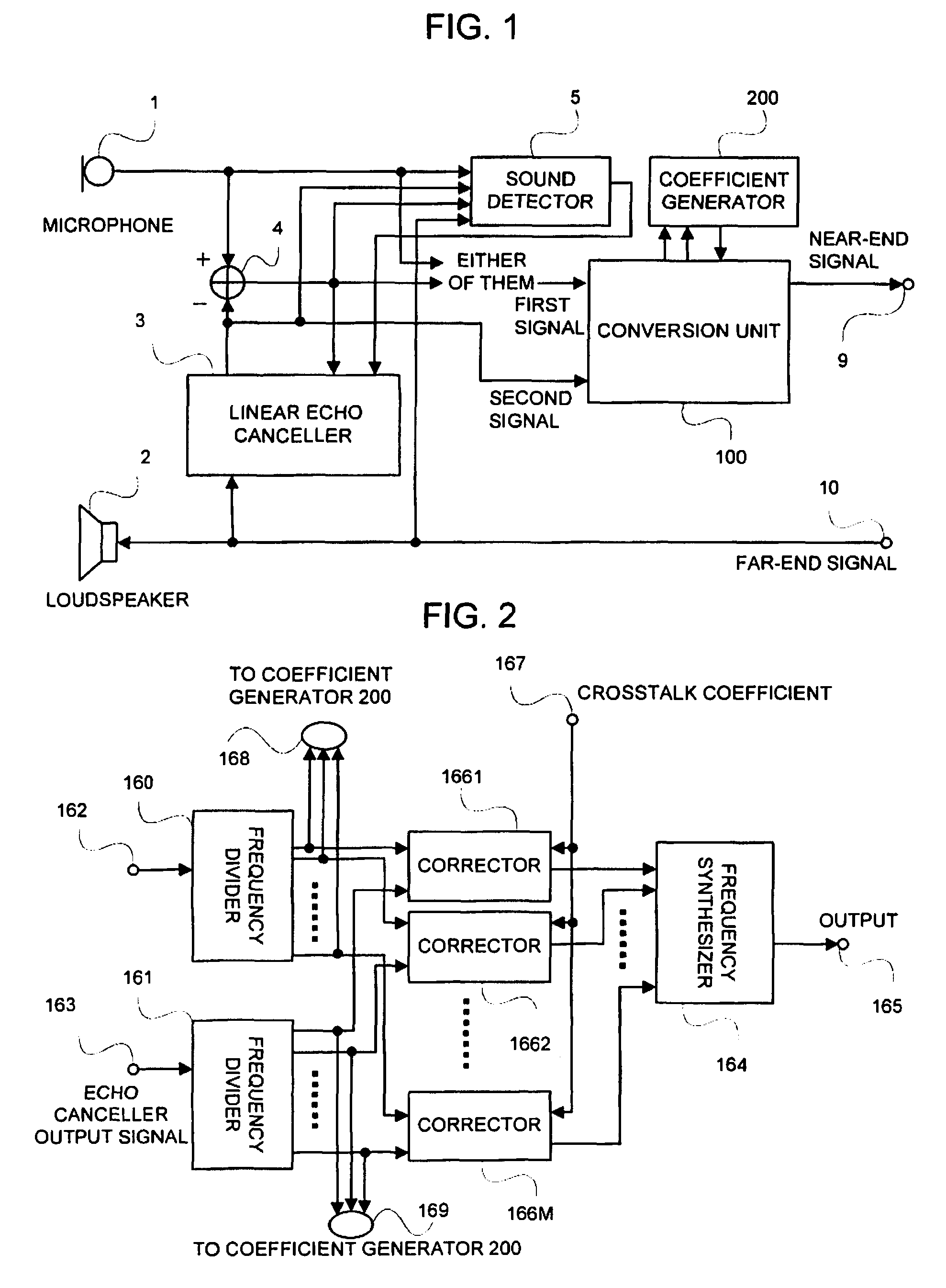
[0164]FIG. 17 is a block diagram of the third example of the present invention. A difference with the first example shown in FIG. 13 is that the spectral subtraction unit 6 is replaced with a spectral suppression unit 7. The spectral suppression unit 7 will be explained by employing the figure.

[0165]FIG. 18 is a block diagram illustrating the spectral suppression unit 7. The output signal of the subtracter 4 of FIG. 17 is inputted from an input terminal 72. A Fourier transformer 70 receives the signal inputted from the input terminal 72, calculates an M-point Fourier transform thereof, sends a calculated result (amplitude and phase) as a first Fourier coefficient to Fourier coefficient multipliers 76m (m=1 to M) that correspond to respective frequencies, and simultaneously therewith, sends it to the coefficient generator 200 through the terminal 168. On the other hand,...


PUM


Abstract

The coefficient generating section receives a first signal which is the output signal of the microphone of a signal generated by subtracting the output signal of a linear echo canceller from the output signal of the microphone and a second signal which is the output signal of the linear echo canceller. The coefficient generating section detects the minimum value of the variation with time of the ratio of the amplitude of the first signal to that of the second signal and outputs the value of constant times the detected minimum value as a crosstalk coefficient indicating the degree of crosstalk of the echo. The converting section corrects the first signal according to the crosstalk coefficient and the second signal to generate a near-end signal which is the resultant signal of when the echo is removed from the first signal and outputs the near-end signal to an output terminal.

Description

APPLICABLE FIELD IN THE INDUSTRY[0001]The present invention relates to a technology of suppressing an echo in a situation in which loud-speaking and sound pickup are carried out simultaneously, for example, a hands-free telephone set and an apparatus for recognizing sound while reproducing car stereo.BACKGROUND ART[0002]An exemplary configuration of a first technology for suppressing the echo caused by acoustic system coupling between a sound pickup apparatus and a loudspeaker in the hands-free telephone set is shown in FIG. 30. In FIG. 30, a sound signal (which is called a far-end signal) of a call partner being applied to an input terminal 10 is produced as a far-end sound from a loudspeaker 2. The necessary sound, for example, speaker's voice (which is called near-end sound) enters a microphone 1, and simultaneously therewith, the far-end sound produced from the loudspeaker 2 leaks into it through space. This crosstalk is called an echo. Further, the acoustic transmission system ...

Claims


Application Information

Patent Timeline
Patent Type & Authority Patents(United States)
IPC IPC(8): H04M9/08
CPCH04B3/23H04M9/082
Inventor HOSHUYAMA, OSAMU
Owner NEC CORP
Why Eureka
Try Eureka