Echo suppression mechanism

A technology of echo suppression and body, applied in the direction of echo reduction, telephone structure, support structure installation, etc., can solve the problem of sound quality deterioration

Inactive Publication Date: 2005-05-04
PANASONIC CORP
View PDF0 Cites 0 Cited by
  • Summary
  • Abstract
  • Description
  • Claims
  • Application Information

AI Technical Summary

Problems solved by technology

[0003] In more detail, as Figure 4 As shown, in a portable wireless device whose body is composed of a cover 31 and a box 32, an I / O interface 34 formed on a printed circuit board 33 is sandwiched between the cover 31 and the box 32, wherein the I / O The side of the interface 34 facing the case 32 and the side of the I / O interface 34 facing the cover 31 form slits parallel to the outer end 41 of the I / O interface through which received sound leaks from the receiver and reaches the transmitter (microphone) 35 produces an echo, which leads to deterioration of the sound quality
[0004] Generally, such as Figure 4 As shown, in the portable wireless device whose body is composed of a cover and a case 32, the portable wireless device adopts a device including a battery for fixing the battery 38 when the battery 38 is put into the battery compartment 37 formed on the case 32. The way of the battery hook 39, wherein there are gaps between the battery hook 39 and the box 32 and between the battery hook 39 and the protective box 40, through which the received sound leaks from the receiver and reaches the transmitter (microphone) 35 to generate an echo , resulting in deterioration of sound quality

Method used


Image

  • Echo suppression mechanism
  • Echo suppression mechanism
  • Echo suppression mechanism

Examples


Embodiment Construction

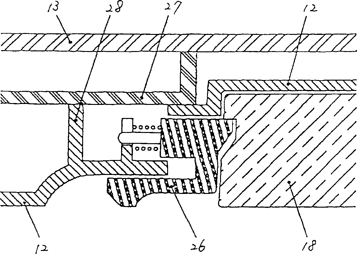
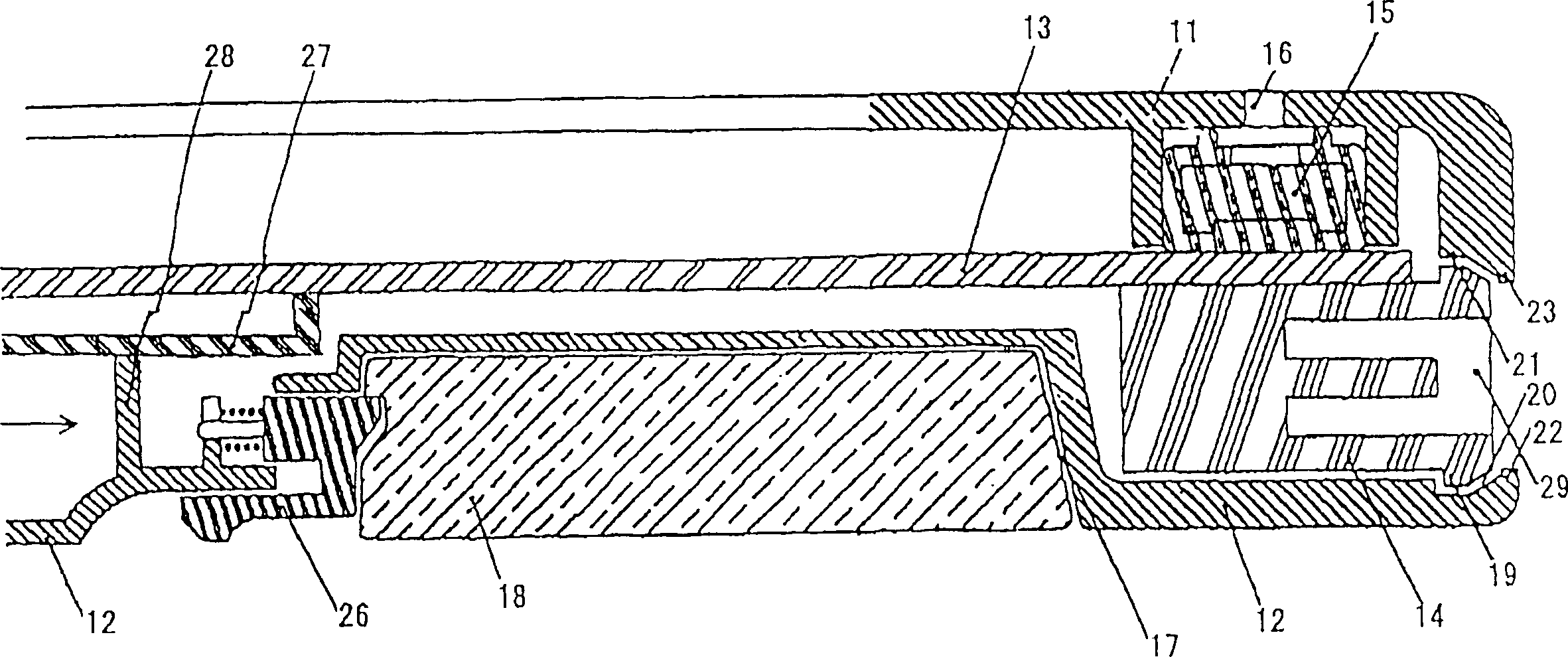
[0021] refer to figure 1 and 2 Embodiments of the present invention will be described.

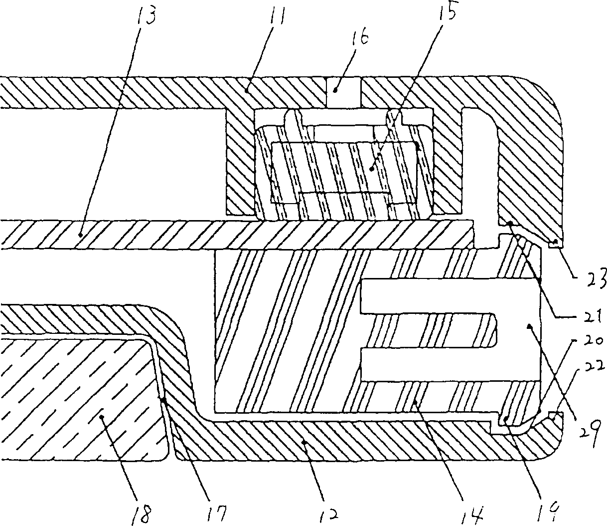
[0022] figure 1 is a cross-sectional view of a portable wireless device showing the structure of an echo suppressing mechanism according to an embodiment of the present invention.

[0023] refer to figure 1 , the body of the portable wireless device is composed of a cover 11 and a box 12, and an I / O (input / output) interface 14 formed on a printed circuit board 13 is sandwiched between the cover 11 and the box 12. A transmitter (microphone) 15 formed on the printed circuit board 13 is connected to the cover 11 and a speaking port 16 is formed on the cover 11 . The box 12 is provided with a battery compartment 17 for accommodating a battery 18 .

[0024] figure 1 with in Figure 4 The common structure difference in is that a rib 19 is formed on the side of the I / O interface 14 facing the box 12 and the side of the I / O interface 14 facing the cover 11, while the box 12 and the cove...


PUM


Abstract

The body of the portable wireless device is composed of a cover 11 and a box 12. The I / O interface 14 on the printed circuit board 13 is sandwiched between the cover 11 and the box 12. The transmitter 15 on the printed circuit board 13 is connected to the cover 11, and a transmission port 16 is formed on the cover 11. A battery compartment 17 is formed on the box 12 for accommodating the battery 18 . Ribs 19 are formed on the side of the I / O interface 14 facing the box 12 and the side of the I / O interface 14 facing the cover 11 , and grooves 20 and 21 for receiving the ribs are formed on the box 12 and the cover 11 . Furthermore, ribs 22 and 23 are formed on the outer end side of the box 12 facing the I / O interface and the outer end side of the cover 11 facing the I / O interface.

Description

technical field [0001] The present invention relates to an echo suppressing mechanism, and in particular to an echo suppressing mechanism equipped with ribs for blocking received sound propagating from a receiver (speaker) in a portable wireless device via a space inside a body and Prevent echo or howling noise (hereinafter referred to as echo) from reaching a transmitter (microphone). Background technique [0002] Fig. 5A has shown the perspective view when the operating panel of a common portable wireless device faces up, and Fig. 5B has shown the perspective view when the back of the common portable wireless device is turned up, Figure 5C A cross-sectional view of a conventional portable radio device is shown. As shown in Figure 5A, a main unit body 50 is equipped with an earpiece 52 for a receiver (speaker) 51 and a mouthpiece 36 for a microphone 35 on the operating side, and an I / O interface 34 is installed at its end . The receiver 51 transmits the received sound fr...

Claims


Application Information

Patent Timeline
IPC IPC(8): H05K7/02H04B1/38H04M1/02H04M1/20H04W88/02H05K5/02H05K7/14
CPCH04M1/20H04M1/0262
Inventor 北村敏康山本孝一大里恭史小野秀夫
Owner PANASONIC CORP
Why Eureka
Try Eureka