Echo suppressing system, echo suppressing method, recording medium, echo suppressor, sound output device, audio system, navigation system and mobile object

a technology of echo suppression and echo suppression, applied in the field of echo suppression system, echo suppression method, recording medium, echo suppressor, sound output device, etc., can solve the problems of serious size problem, increase in device cost and size,

Active Publication Date: 2012-12-25
FUJITSU LTD
View PDF37 Cites 0 Cited by
  • Summary
  • Abstract
  • Description
  • Claims
  • Application Information

AI Technical Summary

Benefits of technology

[0007]An echo suppressing system includes: a sound output device for outputting sound based on a sound signal, including a passing section for allowing passage of a component of a different frequency band for each of a plurality of sound signals, and a plurality of sound output sections, each of which outputs sound based on each of the plurality of sound signals passed through the passing section; a summer for summing the plurality of sound signals passed through the passing section to generate a reference sound signal; a sound input device for converting input sound into a sound signal; and an echo suppressor for suppressing echo based on the sound output by the sound output device from the sound input to the sound input device, including an input section to which a sound signal is input from the sound input device as an observation sound signal, and a correction section for correcting the observation sound signal so as to suppress echo included in the observation sound signal based on the observation sound signal and the reference sound signal.

Problems solved by technology

In voice recognition for the conventional car navigation system, for example, a speaker presses down a talking switch before starting a speech, which silences the car navigation system, preventing the sound output by a loudspeaker of the car navigation system from being transferred to a microphone as echo, which may be a cause of false voice recognition.
However, the echo suppressing method requires a suppression mechanism corresponding to each channel and increases in cost and size of a device.
The problem of size is serious especially when the device is applied to a car navigation system for which the installation space is largely limited.

Method used


Image

  • Echo suppressing system, echo suppressing method, recording medium, echo suppressor, sound output device, audio system, navigation system and mobile object
  • Echo suppressing system, echo suppressing method, recording medium, echo suppressor, sound output device, audio system, navigation system and mobile object
  • Echo suppressing system, echo suppressing method, recording medium, echo suppressor, sound output device, audio system, navigation system and mobile object

Examples


embodiment 1

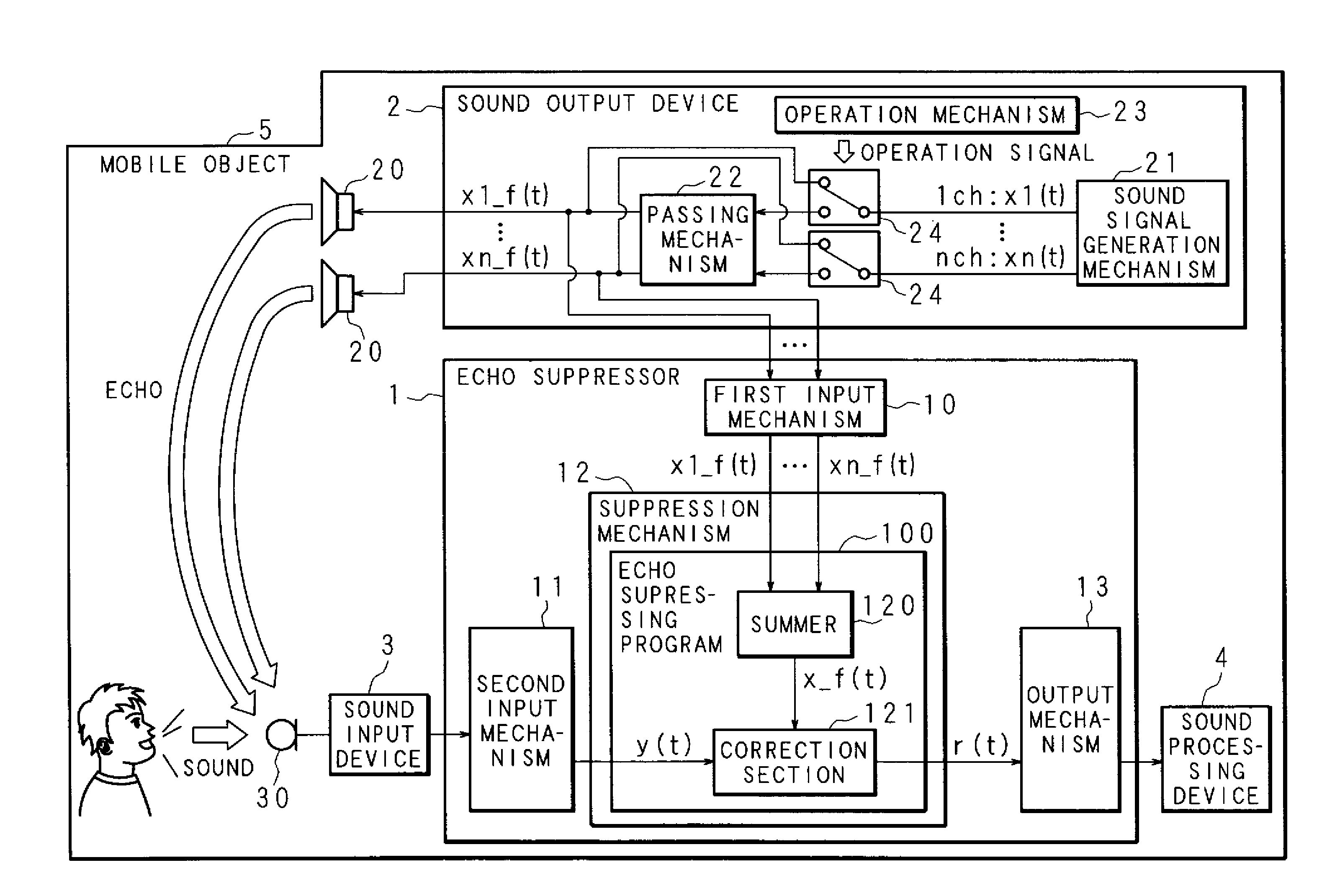
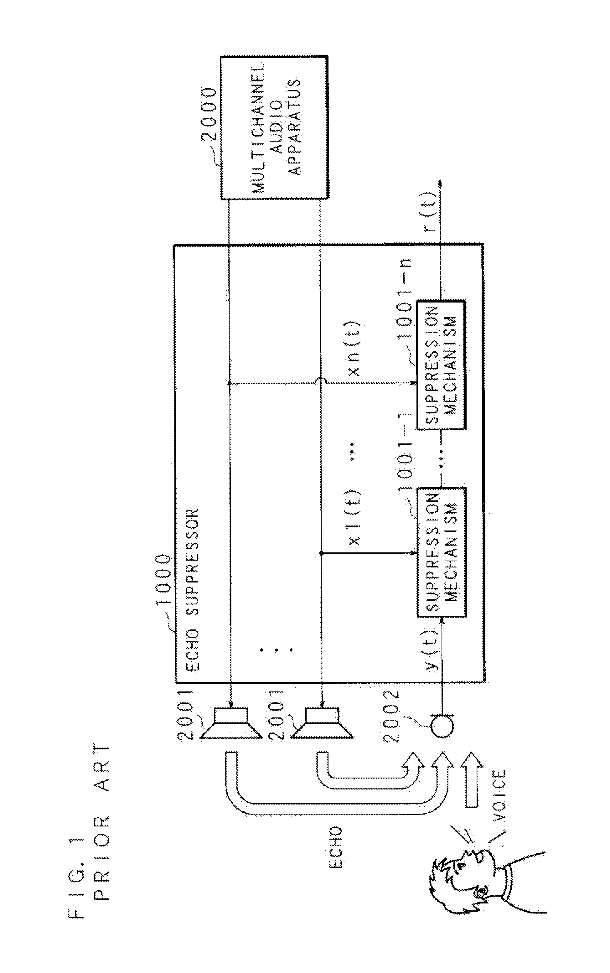
[0038]FIG. 1 is a schematic diagram illustrating the conventional first echo suppressor. An echo suppressor is denoted by 1000 in FIG. 1. The echo suppressor 1000 outputs sound signals of a plurality of channels output from a multichannel audio apparatus 2000 to a plurality of loudspeakers 2001, 2001, . . . , each of the loudspeakers 2001, 2001, . . . outputting sound based on each sound signal. The echo suppressor 1000 then removes echo based on the output sound of a plurality of channels from the sound received at a microphone 2002. Echo is removed by suppressing the echo corresponding to each of reference sound signals x1(t), . . . , xn(t) based on the output sound of a plurality of channels (n) from an observation sound signal y(t) based on the received sound, at a plurality of suppression mechanisms (echo cancellers) that correspond to the reference sound signals x1(t), . . . , xn(t) of the respective channels.

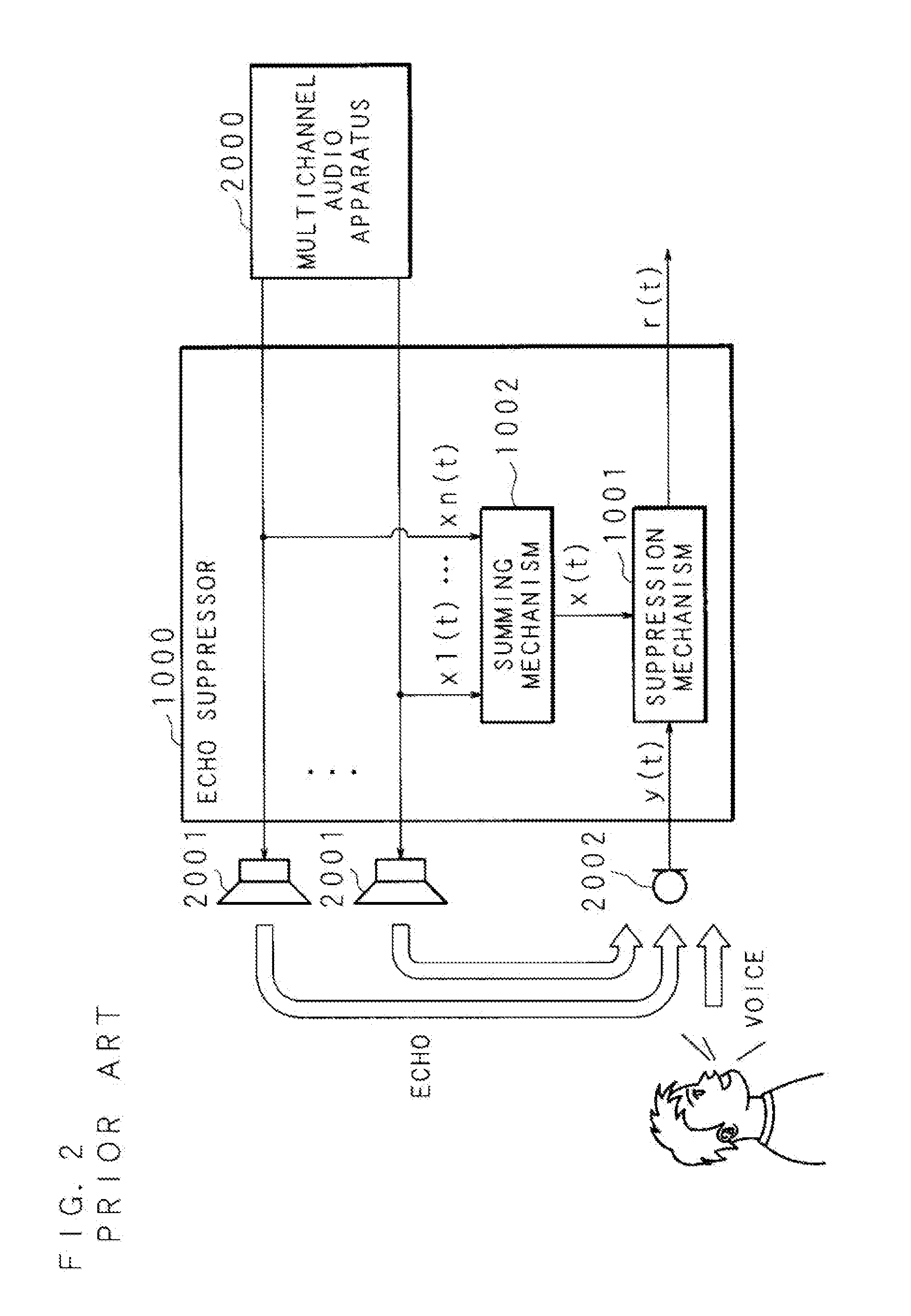
[0039]A form of the echo suppressor other than that of FIG. 1, in wh...

embodiment 2

[0073]Embodiment 2 is an example where, in Embodiment 1, a processed sound signal obtained by processing an original sound signal using a given method is used to realize efficient filtering for sound signals of a plurality of channels. In Embodiment 2, an example is described where the present embodiment is applied to a pseudo 5-channel stereo system with a first sound signal of L (Left) channel, a second sound signal of R (Right) channel, a chord signal of C (Center) channel which is the sum of the first sound signal and the second sound signal, a delayed first sound signal of sL (at the operation Surround Left) channel which is obtained by delaying the first sound signal by a given time, and a delayed second sound signal of sR (at the operation Surround Right) channel which is obtained by delaying the second sound signal by a given time. In the pseudo 5 channels, the first sound signal and the second sound signal are original signals, while the chord signal, the delayed first soun...

embodiment 3

[0082]Embodiment 3 is an example where, in Embodiment 1, for sound signals of a plurality of channels generated by a sound signal generating mechanism, a component of a frequency band corresponding to a preset removal band such as a frequency band corresponding to voice uttered by a person does not pass through for any sound signal, and the double talk or the single talk is detected based on the component of the frequency band corresponding to the removal band.

[0083]In the description below, parts similar to those in Embodiment 1 are denoted by reference codes similar to those in Embodiment 1, and will not be described in detail. Since the configuration example of the echo suppressing system in Embodiment 3 is similar to that of Embodiment 1 illustrated in FIG. 4, reference shall be made to Embodiment 1 and description thereof will not be repeated here.

[0084]FIG. 15 is a functional block diagram illustrating an example of the passing mechanism 22 of the sound output device 2 accordi...


PUM


Abstract

An echo suppressing system includes: a sound output device for outputting sound based on a sound signal, including a passing section for allowing passage of a component of a different frequency band, and a plurality of sound output sections, each of which outputs sound based on each of the plurality of sound signals passed through the passing section; a summer for summing the plurality of sound signals to generate a reference sound signal; a sound input device for converting input sound into a sound signal; and an echo suppressor for suppressing echo based on the sound output by the sound output device, including an input section to which a sound signal is input from the sound input device as an observation sound signal, and a correction section for correcting the observation sound signal so as to suppress echo included in the observation sound signal.

Description

CROSS-REFERENCE TO RELATED APPLICATIONS[0001]This application is a continuation, filed under U.S.C. §111(a), of PCT International Application No. PCT / JP2007 / 073776 which has an international filing date of Dec. 10, 2007 and designated the United States of America, and claims priority to PCT International Application No. PCT / JP2007 / 069930, filed on Oct. 12, 2007; the entire disclosures of both international applications being incorporated by reference as a part of this application.TECHNICAL FIELD[0002]The present invention relates to an echo suppressing system including a sound output device for outputting sound based on a sound signal, a sound input device to which sound is input and an echo suppressor for suppressing echo based on the sound output by the sound output device from the sound input to the sound input device, and also relates to an echo suppressing method applied to the echo suppressing system, a recording medium recording an echo suppressing program for realizing the e...

Claims


Application Information

Patent Timeline
Patent Type & Authority Patents(United States)
IPC IPC(8): G10L21/02G10L15/00A61F11/06G10K11/16G10L21/0208
CPCH04R3/02G10L15/20G10L2021/02082
Inventor MATSUO, NAOSHIITOU, TAISUKE
Owner FUJITSU LTD
Why Eureka
Try Eureka