Loading station for transport bags transported in an overhead conveyor system

a conveyor system and loading station technology, applied in the direction of special packaging, packaging type, liquid bottling, etc., can solve the problem of not being able to use the known means for mechanical loading

Active Publication Date: 2013-07-23
DURKOPP FORDERTECHN
View PDF22 Cites 25 Cited by
  • Summary
  • Abstract
  • Description
  • Claims
  • Application Information

AI Technical Summary

Benefits of technology

[0008]This object is achieved according to the invention by a loading station for transport bags transported in an overhead conveyor system, comprising an upper supply rail for the transport bags; a vertical conveyor which adjoins the upper supply rail for supplying the transport bags in a lower loading position; an opening device for opening the transport bags in the lower loading position; and a lower discharge rail which adjoins the vertical conveyor for moving the transport bags away from the lower loading position in a transport direction. As the transport bags are individually moved down from the actual overhead conveyor system into a loading position where they are opened at their upper end, loading from above is very easily possible, for example by means of a transport device for flat goods.

Problems solved by technology

As such transport bags can only by loaded from the side, a mechanical loading is not possible using the known means.

Method used


Image

  • Loading station for transport bags transported in an overhead conveyor system
  • Loading station for transport bags transported in an overhead conveyor system
  • Loading station for transport bags transported in an overhead conveyor system

Examples


Embodiment Construction

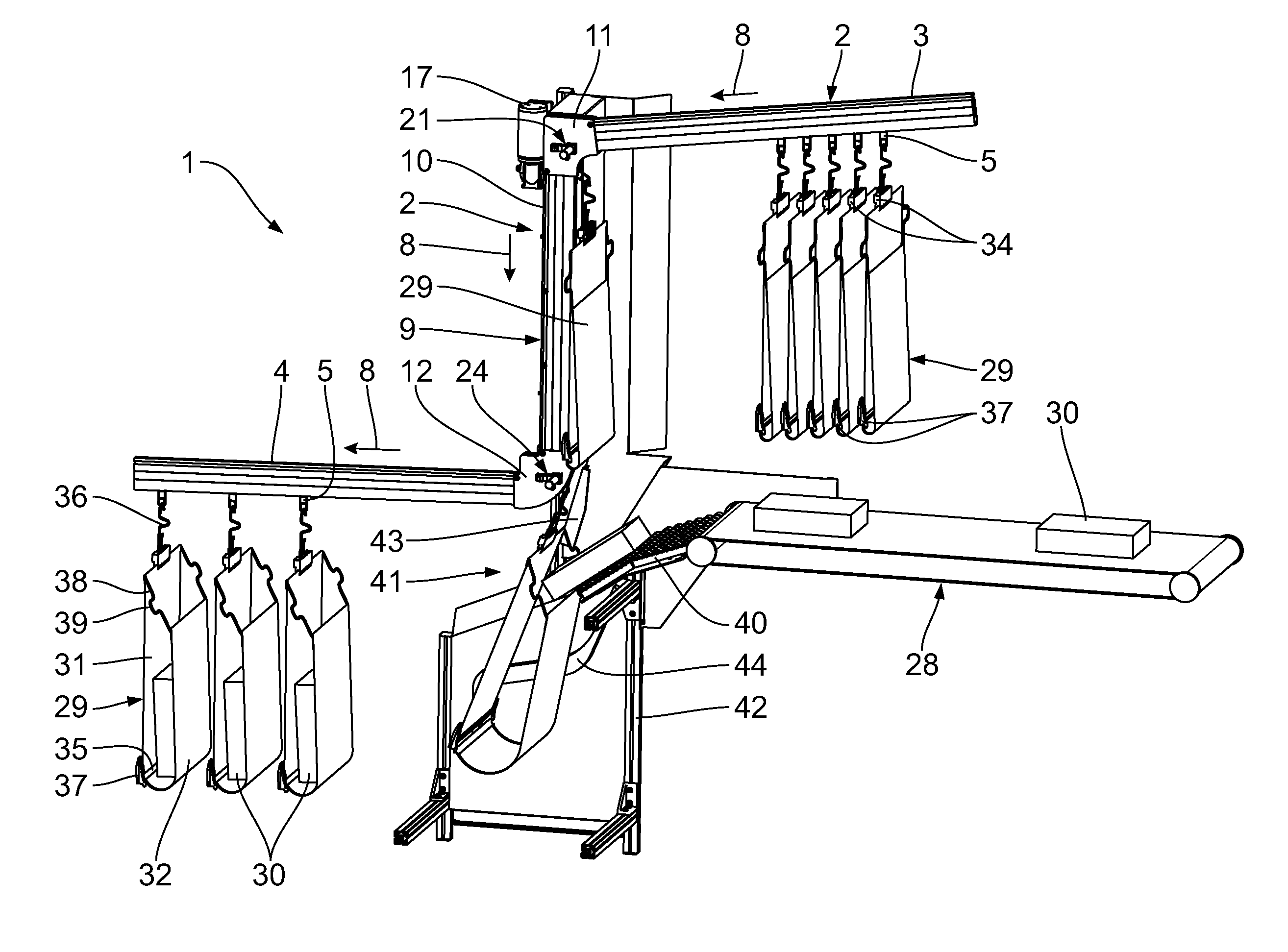
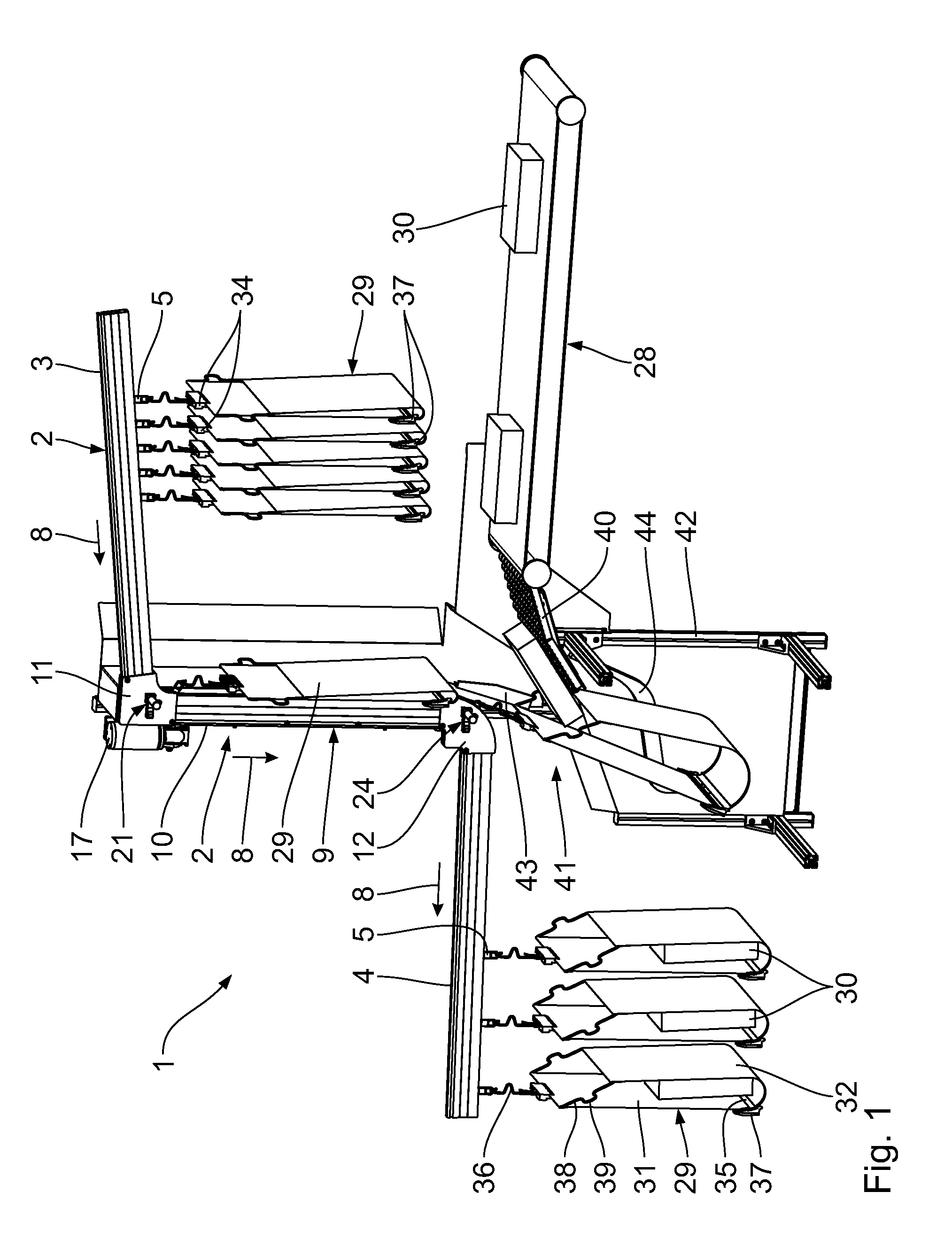
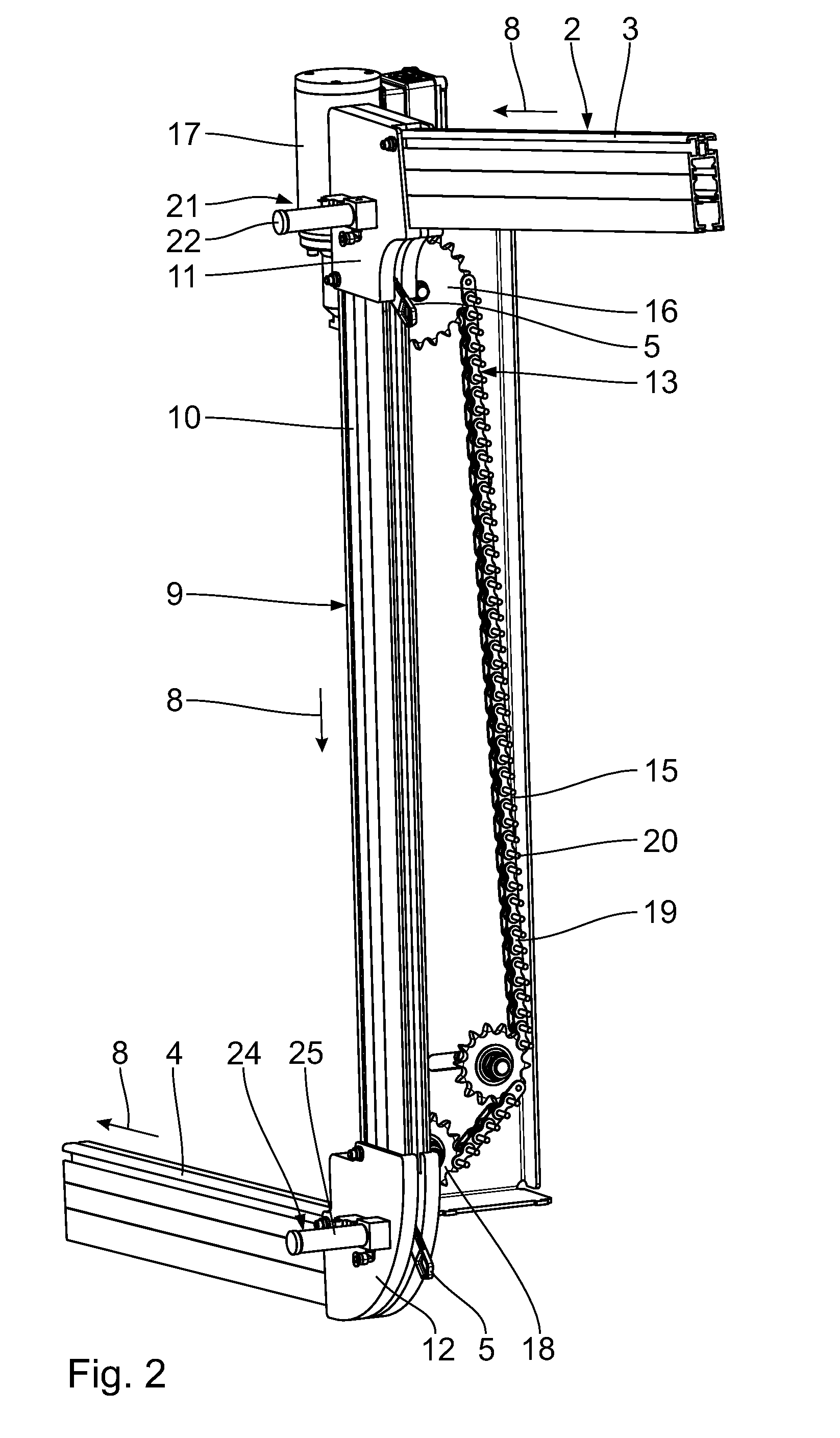
[0014]The loading station 1 shown in FIG. 1 forms part of an overhead conveyor system 2 of which only a supply rail 3 leading into the loading station 1 and a discharge rail 4 leading out of the loading station 1 are shown. In the rails 3, 4 which are designed as hollow profiles, retaining members 5 are mounted by means of track rollers 6, the retaining members 5 comprising a lug-like retaining part 7 projecting downwards and out of the respective rail 3 or 4. Since both the supply rail 3 and the discharge rail 4 are installed in a sloping manner in the transport direction 8, no drive device is required for the retaining members 5 in the rails 3, 4 in the region of the loading station 1. The rails 3, 4, the retaining members 5 as well as corresponding drive devices for the retaining members 5 are also shown and described in EP 1 690 811 A1 to which reference can be made.

[0015]An essential component of the loading station 1 is a vertical conveyor 9. The essential aspect about the ver...


PUM

PropertyMeasurementUnit
flexibleaaaaaaaaaa
mechanicalaaaaaaaaaa
speedaaaaaaaaaa

Abstract

A loading station for transport bags transported in an overhead conveyor system comprises an upper supply rail for the transport bags, a vertical conveyor which adjoins the supply rail for moving the transport bags into a lower loading position, a device for opening the transport bags in the loading position and a lower discharge rail which adjoins the vertical conveyor for discharging the transport bags from the loading position.

Description

BACKGROUND OF THE INVENTION[0001]1. Field of the Invention[0002]The invention relates to a loading station for transport bags transported in an overhead conveyor system.[0003]2. Background Art[0004]In order to be able to transport so-called flat goods such as shoes, packaged pieces of clothing and other packages in overhead conveyor systems, transport bags are used which as a rule comprise carrier hooks which are adapted to be inserted into corresponding retaining members of the overhead conveyor system such as hangers on which clothes are hanging.[0005]Such overhead conveyor systems are known for example from EP 1 690 811 A1. In such overhead conveyor systems, retaining members are transported in rails by means of driven chains, the retaining members comprising lower lug-like retaining parts into which hangers are inserted. Such hangers are usually used to transport pieces of clothing but also the mentioned transport bags.[0006]Furthermore, transport bags are known which consist of...

Claims


Application Information

Patent Timeline
Patent Type & Authority Patents(United States)
IPC IPC(8): B65G17/20B65G47/06
CPCB65G19/025B65G47/61B65G9/002
Inventor JANZEN, PAUL
Owner DURKOPP FORDERTECHN
Why Eureka
Try Eureka