
Clutch device

a technology of clutch and cylinder, which is applied in the direction of mechanically actuated clutches, transportation and packaging, mechanical apparatuses, etc., can solve the problem of greater compactness

Active Publication Date: 2019-09-05
SCHAEFFLER TECH AG & CO KG
View PDF5 Cites 5 Cited by
  • Summary
  • Abstract
  • Description
  • Claims
  • Application Information

AI Technical Summary

Benefits of technology

The patent text describes a three-sub-clutch design for a vehicle transmission. The first sub-clutch is used to connect an internal combustion engine, while the second and third sub-clutches are used to connect different transmission groups. The third sub-clutch is integrated into the rotor and includes a triple clutch, making it compact. The support is connected to the outer disk carrier to which the rotor and other components are connected, further increasing the compactness of the design. The actuation element for the second sub-clutch passes through the first sub-clutch, which ensures proper functioning. The technical effect of this design is a more efficient and compact vehicle transmission system.

Problems solved by technology

In either case, however, there is greater compactness since the bearing location is provided on a component which is likewise designed or arranged with a high degree of compactness as regards the installation space available.

Method used


Image

  • Clutch device
  • Clutch device
  • Clutch device

Examples


Embodiment Construction

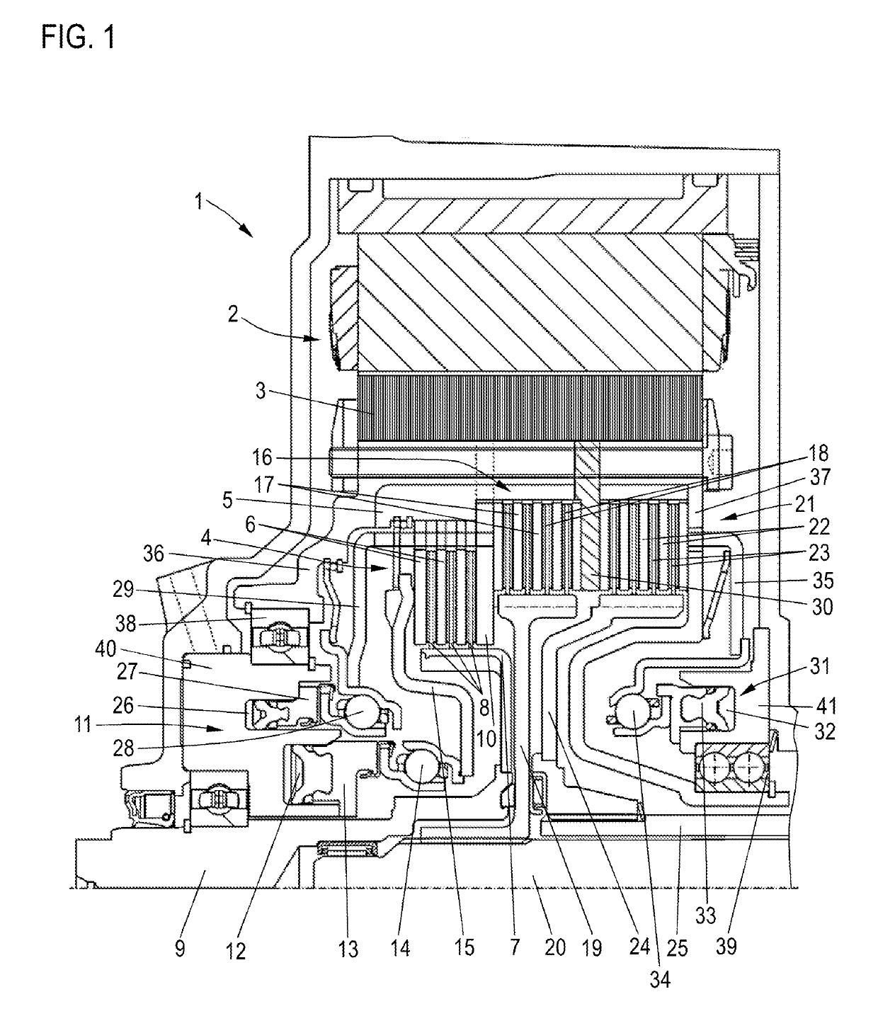
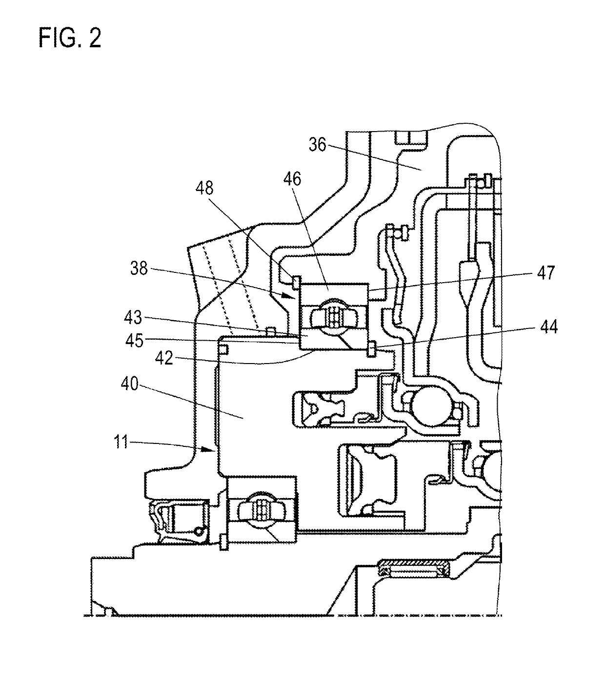
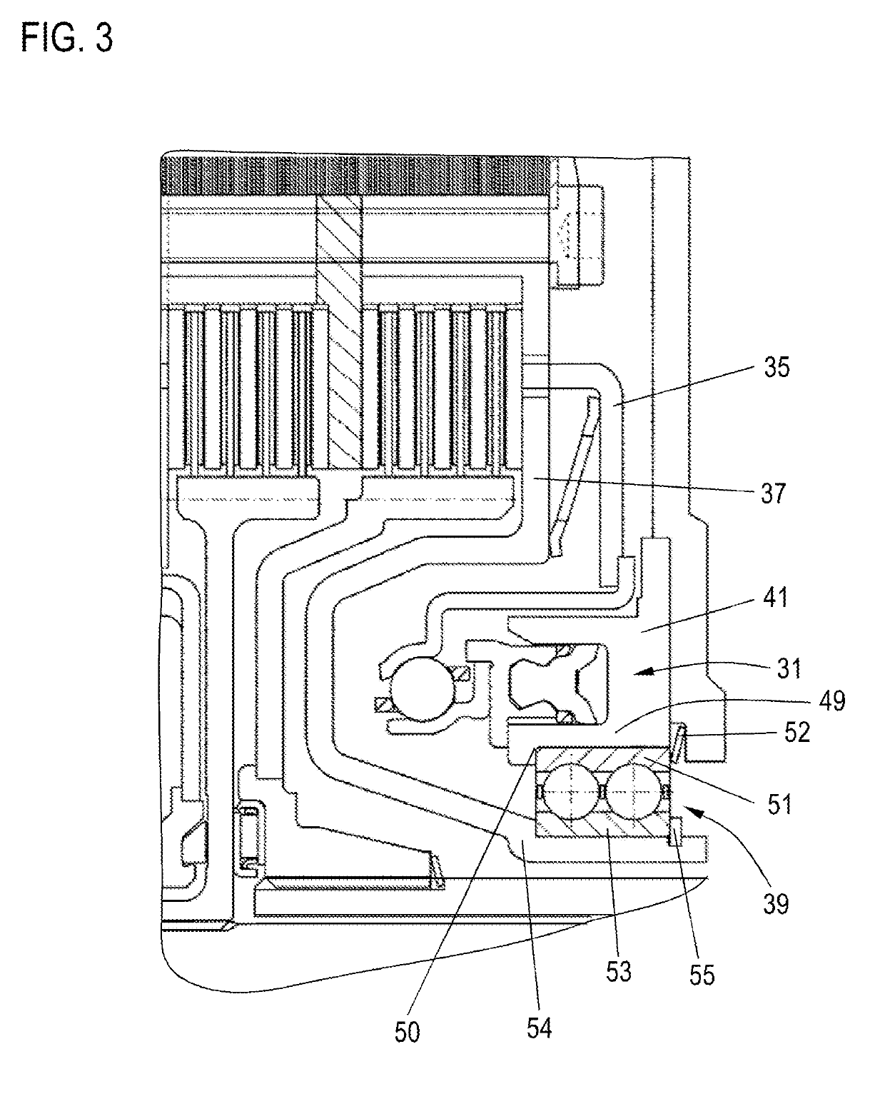
[0026]FIG. 1 shows a clutch device 1 according to the invention with an associated electric machine 2 having a rotor 3. A sub-clutch 4, generally also referred to as the K0 clutch, is provided, having an outer disk carrier 5, on which a plurality of outer disks 6, e.g., steel disks, is arranged. A plurality of inner disks 8, in this case friction disks, is arranged on an inner disk carrier 7. The outer disk carrier 5 is firmly connected to the rotor 3, while the inner disk carrier 7 is connected to a driving hub 9, which is coupled to an internal combustion engine (not shown specifically).

[0027]The outer and inner disks 6, 8 form a disk pack which, since the outer disks are arranged in an axially movable manner on the respective outer and inner disk carrier 5, 7, can be compressed axially against an abutment 10. In this case, there is a frictional connection and hence torque transmission from the rotor 3, via the outer disk carrier 5, the disk pack and the inner disk carrier 7, to t...


PUM


Abstract

A clutch device includes a rotor, a first sub-clutch, a second sub-clutch, and a first actuation device. The rotor has a first axial side and a second axial side. The sub-clutches are arranged within the rotor and each include an outer disk carrier with outer disks and an inner disk carrier with an inner disk engaged between two of the outer disks. The first actuating device is for actuating the first sub-clutch or the second sub-clutch. The first actuating device has a first housing. The rotor first axial side is rotatably mounted on the first housing via a first support.

Description

CROSS-REFERENCE TO RELATED APPLICATIONS[0001]This application is the United States National Phase of PCT Appln. No. PCT / DE2017 / 100984 filed Nov. 17, 2017, which claims priority to German Application No. DE102016223277.0 filed Nov. 24, 2016, the entire disclosures of which are incorporated by reference herein.TECHNICAL FIELD[0002]The disclosure relates to a clutch device which is coupled or can be coupled to the rotor of an electric machineBACKGROUND[0003]As is known, a clutch device of this kind is used to couple the drive of a driving device, e.g., an internal combustion engine, to a transmission. In modern motor vehicles having a hybrid drive, an electric motor, which can likewise be coupled to the transmission by means of a clutch device of this kind in order to enable an electric driving mode, is additionally provided. However, it is furthermore also coupled or capable of being coupled to the internal combustion engine via the output thereof in order to assist or drive said engi...

Claims


Application Information

Patent Timeline
Patent Type & Authority Applications(United States)
IPC IPC(8): F16D21/06H02K7/00H02K7/108F16D25/10F16D25/0638F16D13/52B60K6/387F16C19/00
CPCF16D21/06H02K7/006H02K7/108F16D25/10F16D25/0638F16C2326/01B60K6/387F16C19/00F16D2021/0661F16D2021/0692B60Y2200/92F16D13/52B60K6/40F16D25/082B60K6/48B60K2006/4825Y02T10/62
Inventor LORENZ, ELMAR
Owner SCHAEFFLER TECH AG & CO KG
Learn More