Method and arrangement for measuring and testing a vehicle frame

a vehicle frame and measurement method technology, applied in the direction of mechanical measuring arrangements, optical radiation measurement, instruments, etc., can solve the problems of measurement errors, labor-intensive and time-consuming, and measurement errors in the measurement of certain deformations of the frame, so as to achieve less time-consuming and labor-intensive measuring and testing, and high measurement accuracy in measurement and testing.

Active Publication Date: 2013-08-08
HAWEKA
View PDF0 Cites 3 Cited by
  • Summary
  • Abstract
  • Description
  • Claims
  • Application Information

AI Technical Summary

Benefits of technology

[0007]The object of this invention is to make available a method and an arrangement for measuring and testing a vehicle frame which allow less time-consum

Problems solved by technology

It is disadvantageous in the known methods for measuring and testing of vehicle frames that possibly add-on parts on the frame must be removed in order to attach the reflector to the frame; this is labor-intensive and time-consuming.
Since the laser source projects over the vehicle wheel rim to the outside, th

Method used


Image

  • Method and arrangement for measuring and testing a vehicle frame
  • Method and arrangement for measuring and testing a vehicle frame
  • Method and arrangement for measuring and testing a vehicle frame

Examples


Embodiment Construction

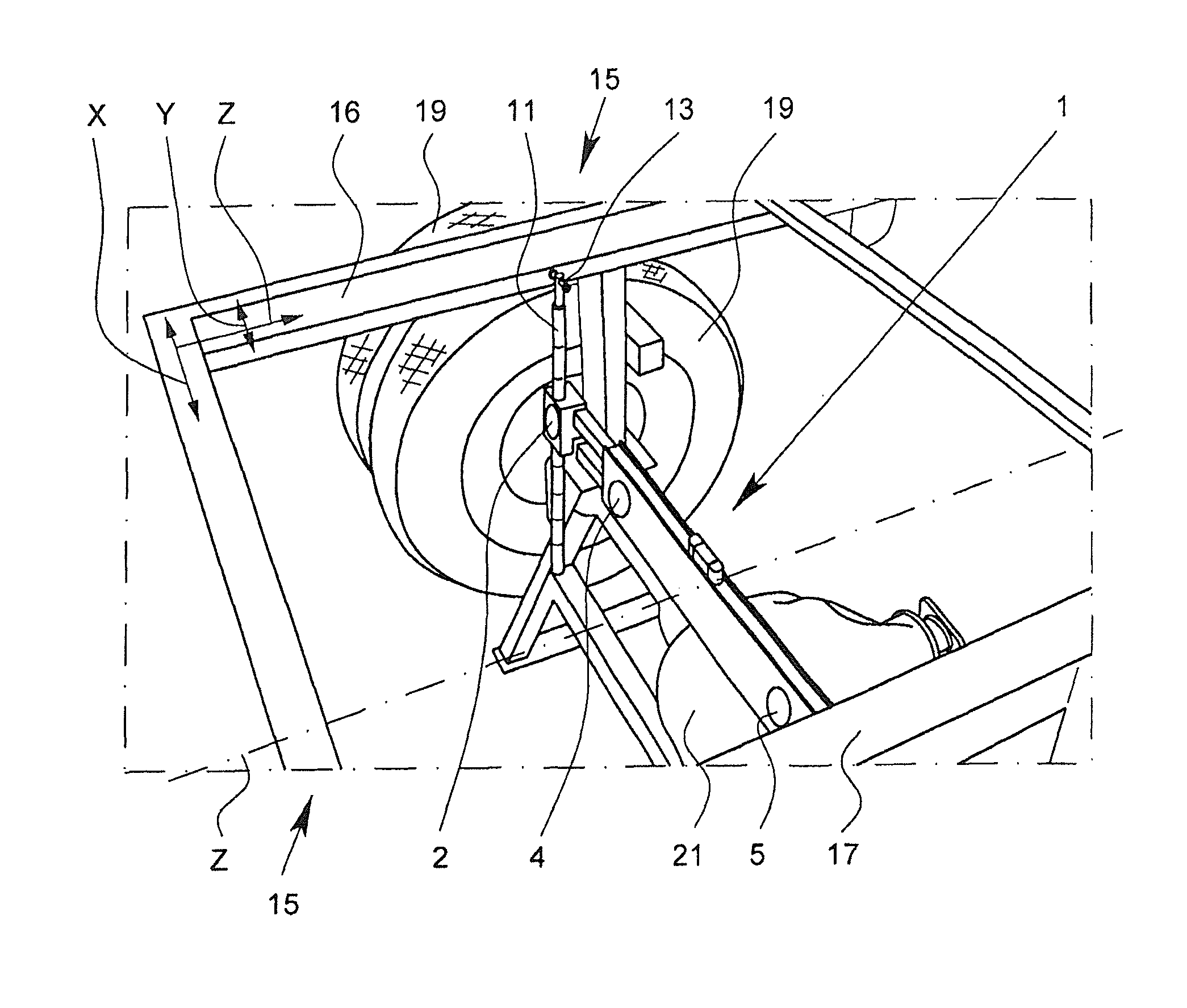
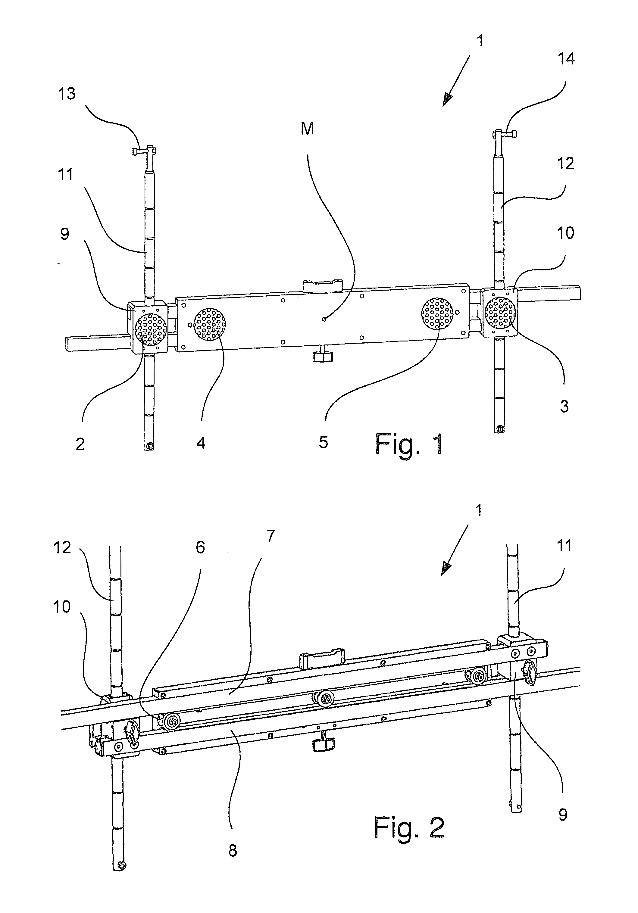
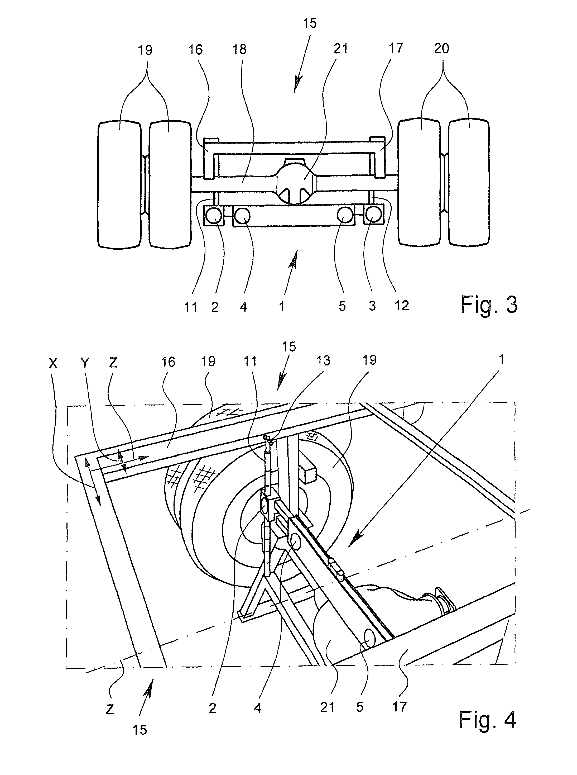
[0032]FIG. 1 shows a reflector support 1 with two outer reflectors 2, 3 and two inner reflectors 4, 5. As follows from FIG. 2, which shows the reflector support 1 of FIG. 1 from the rear after removing a covering sheet, the reflector support 1 has a belt 6 via which two horizontal rods 7, 8 are coupled to one another. The upper vertical rod 7 is permanently connected to a box profile 9 while the lower horizontal rod 8 is permanently connected to a box profile 10. The two box profiles 9, 10 are guided vertically adjustably on vertical rods 11, 12, the upper horizontal rod 7 being guided on the box profile 10 and the lower horizontal rod 8 being guided on the box profile 9. When the box profile 10 is pulled to the outside with the vertical rod 12, by means of belt 6, the box profile 9 with the right vertical rod 11 is automatically shifted to the other side by the deflection of the belt 6. The same principle can be implemented by racks which are coupled via a pinion and which are conn...


PUM


Abstract

A method for measuring and testing a vehicle frame (15), in particular a commercial vehicle or bus frame, wherein a radiation source and a radiation receiver are arranged in front of the frame (15) and radiation is beamed from the radiation source toward the frame (15) and onto a reflector support (1) having at least one reflector (2, 3, 4, 5). The reflector (2, 3, 4, 5) is assigned to a part of the frame (15), and the radiation is reflected by the reflector (2, 3, 4, 5) to the radiation receiver and a measuring device determines location coordinates of the reflector (2, 3, 4, 5) at different measuring points of the frame part. A substantially non-deformed section (A) of the frame part is ascertained from the resulting measuring points (P) and the variation of the measuring points (P) from the non-deformed section (A) is determined.

Description

BACKGROUND OF THE INVENTION[0001]1. Field of the Invention[0002]The invention relates to a method and arrangement for measuring and testing a vehicle frame, especially a truck frame or bus frame.[0003]2. Description of Related Art[0004]The prior art already discloses methods for measuring and testing a vehicle frame, on a rim of a vehicle wheel an axle measurement holder for a laser source and for a measurement scale being attached from the outside. From the outside, a reflector is attached to the frame and reflects a laser beam emitted by the laser source in the direction to the measurement scale on the axle measurement holder. If the reflector is attached to different locations of the frame and a laser beam measurement is taken at each location, the deformation of the frame can be deduced from the deviation of the laser incidence points on the measurement scale. There is a corresponding laser source with a measurement channel and a reflector on each longitudinal side for measuring...

Claims


Application Information

Patent Timeline
IPC IPC(8): G01B11/27
CPCG01B5/0025G01B11/16G01B11/275G01B11/272G01B2210/306G01M17/04G01B2210/24
Inventor WARKOTSCH, DIRKEBERLE, ALEXANDERJANZ, TILOSCHENITZKI, HARALD
Owner HAWEKA
Why Eureka
Try Eureka