Multi-sectional linear ionizing bar and ionization cell

a technology of ionizing bar and ionization cell, which is applied in the direction of electrostatic separation, spray discharge apparatus, nuclear engineering, etc., can solve the problems of high cost of traditional ionizing cell incorporating a multiplicity of emitter points, high cost of operating and maintaining traditional ionizing cells, and high cost of cda or nitrogen gas consumption during operation, and achieve high cost. , the effect of high cost and high cost of operation and maintenan

Active Publication Date: 2013-07-23
ILLINOIS TOOL WORKS INC
View PDF11 Cites 31 Cited by
  • Summary
  • Abstract
  • Description
  • Claims
  • Application Information

AI Technical Summary

Benefits of technology

[0015]The currently disclosed invention suggests new approaches for linear ionizing bar design that are capable of solving the above-mentioned problems and, thus, are naturally beneficial for FPD industrial (and other) applications.

Problems solved by technology

The use of traditional charge-neutralization ionizing bars of the type described above presents several deficiencies / drawbacks / limitations in trying to satisfy the above-described demanding requirements for charge neutralization of the FPD industry.
The high cost of traditional ionization cells incorporating a multiplicity of emitter points due to the need for (1) several individual connectors between a high voltage power supply and the emitter(s), and (2) a relatively complicated air / gas delivery system;
The high cost of operating and maintaining traditional ionization cells, including the cost of (1) cleaning nozzles and emitter points, and (2) high clean dry air (CDA) or nitrogen gas consumption during operation;
Common problems encountered by the use of stretched wire emitter ionizers (linear ionizers) can be due to wire sagging and vibration effects.
In addition, high velocity air streams directly blowing ions off of the linear wire emitters exacerbate the inherent problem of wire vibration and accelerate contamination of the wire emitter (as a result of particles attracted to the wire from entrained ambient air).
Both factors make wire emitters prone to breakage and complicate linear ionizer bar maintenance.

Method used


Image

  • Multi-sectional linear ionizing bar and ionization cell
  • Multi-sectional linear ionizing bar and ionization cell
  • Multi-sectional linear ionizing bar and ionization cell

Examples


Embodiment Construction

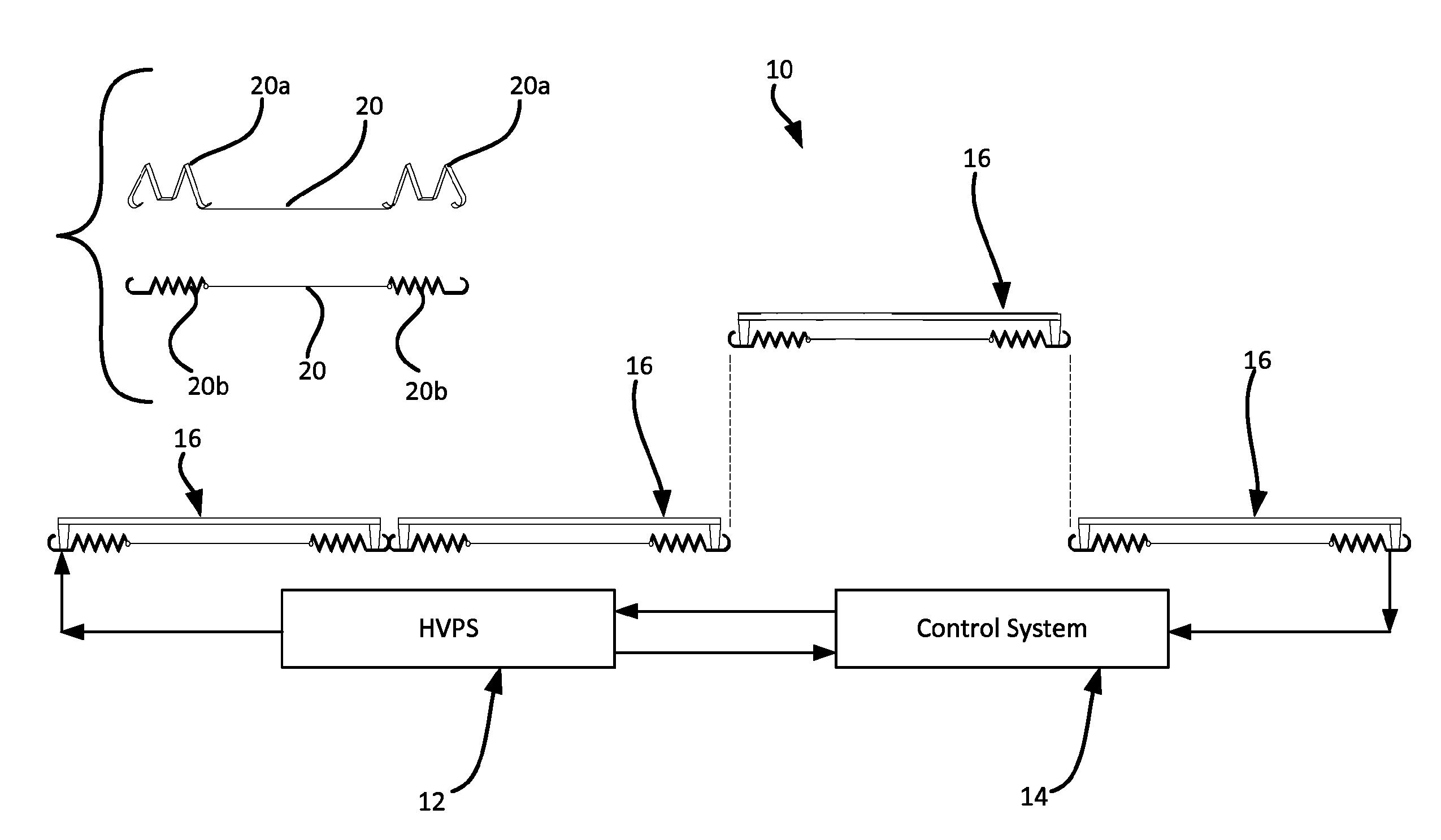
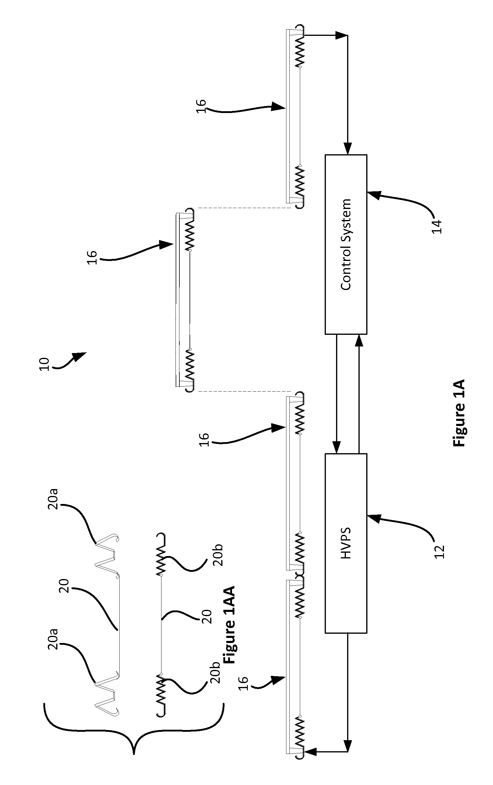
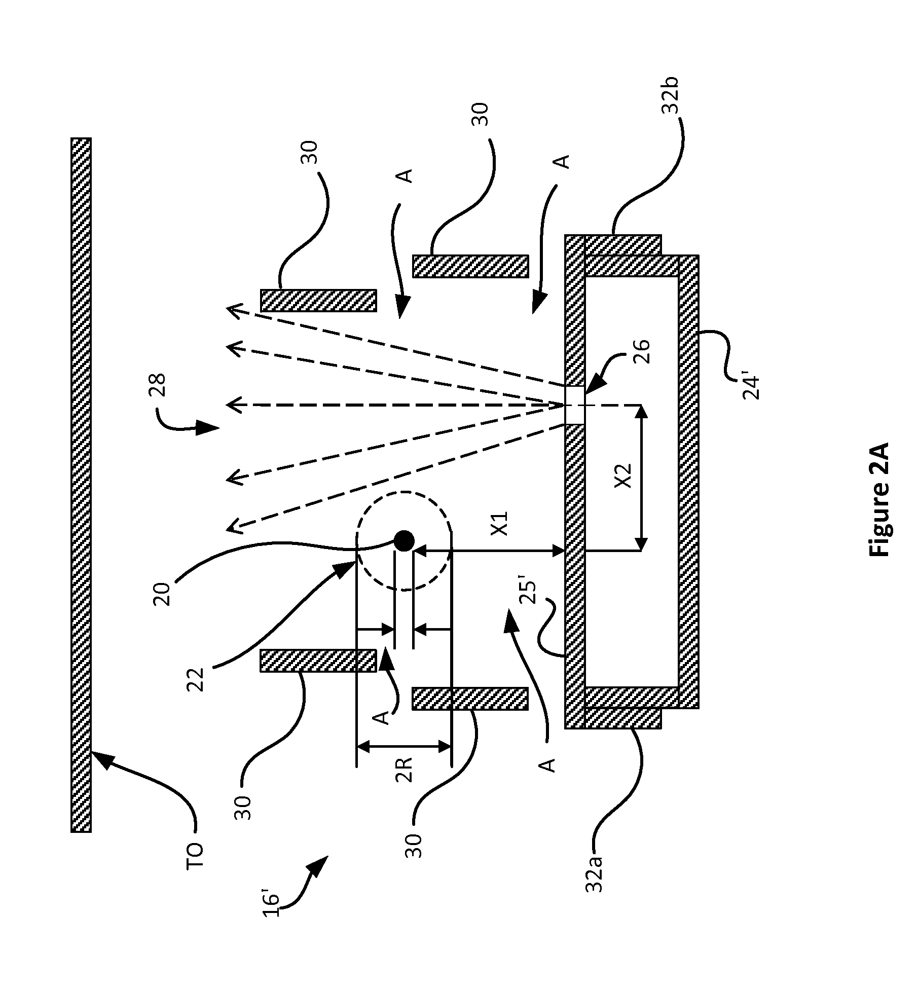
[0035]With joint reference to all of the Figures, the inventive multi-sectional linear ionizing bar 10 preferably comprises at least three primary elements: at least one ionization cell 16 with at least one axis-defining linear ion emitter 20 for establishing an ion plasma region (or ion cloud) 22 along the length thereof, a manifold 24 for receiving gas from a source and for delivering same past linear ion emitter(s) 20 such that substantially none of the gas flows into the plasma region, and means for receiving (20a and / or 20b) ionizing voltage from a suitable power supply 12 (optionally, with a suitable control system 14) and delivering same to linear ion emitter(s) 20 to thereby establish an ion plasma region 22 having an outer peripheral boundary.

[0036]With primary reference to FIGS. 1A and 1AA, one may see preferred schematic representations of an inventive multi-sectional linear ionizing bar 10 (using either coil 20b or flat 20a spring options) with associated high-voltage po...


PUM


Abstract

A multi-sectional linear ionizing bar with at least four elements is disclosed. First, disclosed bars may include at least one ionization cell with at least one axis-defining linear ion emitter for establishing an ion cloud along the length thereof. Second, disclosed bars may include at least one reference electrode. Third, disclosed bars may include a manifold for receiving gas or air from a source and for delivering same past the linear emitter(s) such that substantially none of the gas / air flows into the ion cloud. Fourth, disclosed bars may include means for receiving the ionizing voltage and for delivering same to the linear emitter(s) to thereby establish the ion cloud. In this way, disclosed ionizing bars may transportions from the plasma region toward a charge neutralization target without inducing substantial vibration of the linear emitter and without substantial contaminants from the gas / air flow reaching the linear emitter.

Description

CROSS REFERENCE TO RELATED CASES[0001]This application claims the benefit under 35 U.S.C. 119(e) of the following U.S. Provisional Patent Applications: U.S. Application Ser. No. 61 / 584,173 filed Jan. 6, 2012 and entitled “MULTI-SECTIONAL LINEAR IONIZING BAR—LINEAR IONIZER”; and U.S. Application Ser. No. 61 / 595,667 filed Feb. 6, 2012 entitled “MULTI-SECTIONAL LINEAR IONIZING BAR AND IONIZATION CELL”; which applications are hereby incorporated by reference in their entirety.BACKGROUND OF THE INVENTION[0002]1. Field of the Invention[0003]The present invention is directed to multi-sectional linear ionizing bars and other corona discharge based ionization systems, processes and apparatus for charge neutralization. The invention is particularly useful in (but not limited to) Flat Panel Display (FPD) industrial applications. Accordingly, the general objects of the invention are to provide novel systems, methods and apparatus of such character.[0004]2. Description of the Related Art[0005]Co...

Claims


Application Information

Patent Timeline
Patent Type & Authority Patents(United States)
IPC IPC(8): H01J27/00
CPCH01T19/00H05F3/04H01T23/00
Inventor KLOCHKOV, ALEKSEYGEFTER, PETERHEYMANN, STEVEN BERNARDPARTRIDGE, LESLIE W.BROWN, GREENBERRY BEDFORDANTONELLI, MATTHEW T.
Owner ILLINOIS TOOL WORKS INC
Why Eureka
Try Eureka