Method and apparatus for detecting a short circuit

a short-circuit and detection method technology, applied in short-circuit testing, instruments, air-break switches, etc., can solve the problems of inaccurate detection caused, complicated internal structure of the shorted lead wire detecting apparatus for detecting the short-circuit, and difficulty in estimating the impact of leakage current, etc., to achieve strong negative effect on the accuracy of the measured impedance of the lead wir

Active Publication Date: 2013-07-23
KONINKLIJKE PHILIPS ELECTRONICS NV
View PDF8 Cites 0 Cited by
  • Summary
  • Abstract
  • Description
  • Claims
  • Application Information

AI Technical Summary

Benefits of technology

[0008]Based on the understanding of the prior art and the problems described above, it would be advantageous to detect the shorted lead wire accurately even if there is a heavy leakage current in the shorted lead wire detecting apparatus.
[0016]The basic idea is to decrease the impedance measurement error caused by the leakage current by calculating the impedance of the lead wire on the basis of two groups of voltage values. One group of voltage values comprises the first voltage and the second voltage, and the other group of voltage values comprises the third voltage and the fourth voltage. Assuming that the leakage current in the circuit remains unchanged when the circuit provides different output voltages via the output terminal, based on the two groups of different voltage values, the impact of the leakage current can be reduced or eliminated by carefully designing the method of deriving the lead wire's impedance. In this way, the impedance of the lead wire can be obtained accurately and then a short in the lead wire can be detected accurately so that a wrong diagnosis may be avoided.

Problems solved by technology

Furthermore, it is difficult to estimate the impact of the leakage current because the internal structure of the shorted lead wire detecting apparatus for detecting the short-circuit may be complicated.
U.S. Pat. No. 3,602,215A1 only provides a solution for detecting failure of a set of lead means, but it cannot solve the problem of inaccurate detection caused by the leakage current in the apparatus for detecting failure of lead means.

Method used


Image

  • Method and apparatus for detecting a short circuit
  • Method and apparatus for detecting a short circuit
  • Method and apparatus for detecting a short circuit

Examples


Embodiment Construction

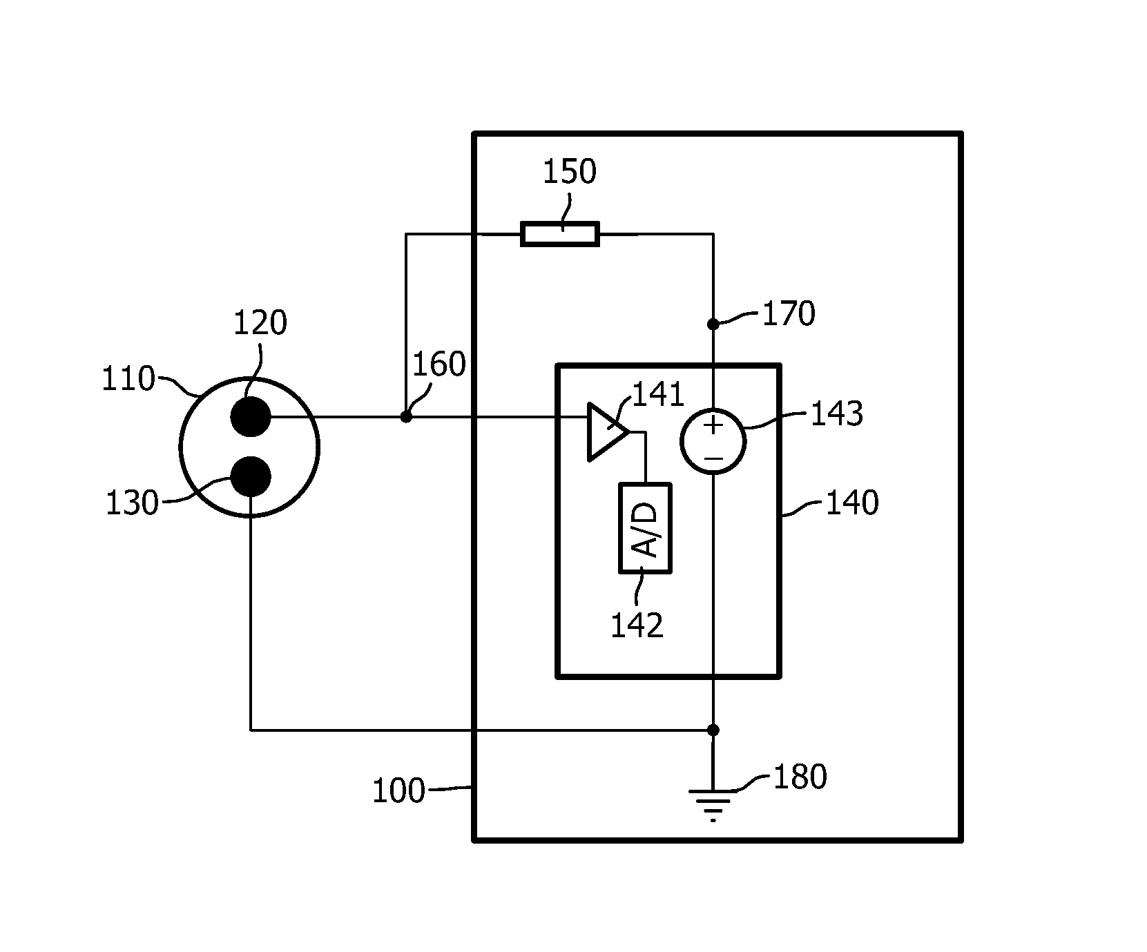
[0031]FIG. 1 depicts a schematic diagram of an apparatus in accordance with an embodiment of the present invention.

[0032]According to an embodiment of a first aspect of the invention, an apparatus 100 for detecting a short-circuit occurring between a signal line 120 and a ground line 130 of a lead wire 110 is provided.

[0033]The lead wire 110 includes the signal line 120 and the ground line 130. To prevent a short-circuit occurring between the signal line and the ground line, there is an insulating layer, such as a rubber layer, covering the signal line, between the signal line and the ground line.

[0034]Referring to FIG. 1, the apparatus 100 comprises a circuit 140 and a resistive element 150.

[0035]The circuit 140 has an output terminal 170, an input terminal 190 and ground 180.

[0036]The output terminal 170 is configured to output a voltage. The circuit 140 can output a voltage via the output terminal 170 in many ways. For example, the circuit 140 comprises a DC (Direct Current) volt...


PUM


Abstract

This invention provides a method and an apparatus for detecting a short-circuit occurring between a signal line and a ground line of a lead wire. The apparatus comprises a circuit and a resistive element. The circuit has an output terminal, an input terminal and ground. One end of the ground line is connected to the ground of the circuit, and the other end of the ground line is disconnected. A first terminal of the resistive element is connected to the output terminal of the circuit. One end of the signal line is connected to a second terminal of the resistive element, and the other end of the signal line is disconnected. The circuit is configured to provide a first voltage via the output terminal and obtain a second voltage via the input terminal connected to a joint of the signal line and the resistive element, to provide a third voltage via the output terminal and obtain a fourth voltage via the input terminal, to derive an impedance of the lead wire from the first voltage, the second voltage, the third voltage, the fourth voltage and an impedance of the resistive element, and to determine whether a short-circuit occurs or not, based on the impedance of the lead wire and a predefined impedance. In this way, the shorted lead wire can be detected with high accuracy.

Description

FIELD OF THE INVENTION[0001]The invention relates to the detection of a short-circuit, in particular to a method and an apparatus for detecting a short-circuit occurring between a signal line and a ground line of a lead wire.BACKGROUND OF THE INVENTION[0002]Electrocardiography is an interpretation of the electrical activity of the heart captured by skin electrodes and externally recorded by an electrocardiograph, and the whole process is a non-invasive recording process.[0003]During an electrocardiographic examination, lead wires are used to connect the electrocardiograph and the skin electrodes to a patient. A typical lead wire includes two metal lines: one is a signal line and the other is a ground line. The signal line and the ground line are separated by an insulating layer, so that the signal line and the ground line cannot touch each other. The signal line is connected to the patient by the skin electrodes and is the main part for transmitting the electronic heart signal; the ...

Claims


Application Information

Patent Timeline
Patent Type & Authority Patents(United States)
IPC IPC(8): G01R31/02G01R31/58
CPCG01R31/021G01R31/025G01R31/58G01R31/52
Inventor MA, XIANG
Owner KONINKLIJKE PHILIPS ELECTRONICS NV
Why Eureka
Try Eureka