
Telecommunication cable equipped with tight-buffered optical fibers

a technology of optical fibers and telecommunication cables, applied in the field of telecommunication cables, can solve the problems of damage to optical fibers, difficult stripping of due lengths, and special tools and installation skills, and achieve the effect of reducing field labor and installation skill

Active Publication Date: 2013-07-23
PRYSMIAN SPA
View PDF9 Cites 10 Cited by
  • Summary
  • Abstract
  • Description
  • Claims
  • Application Information

AI Technical Summary

Benefits of technology

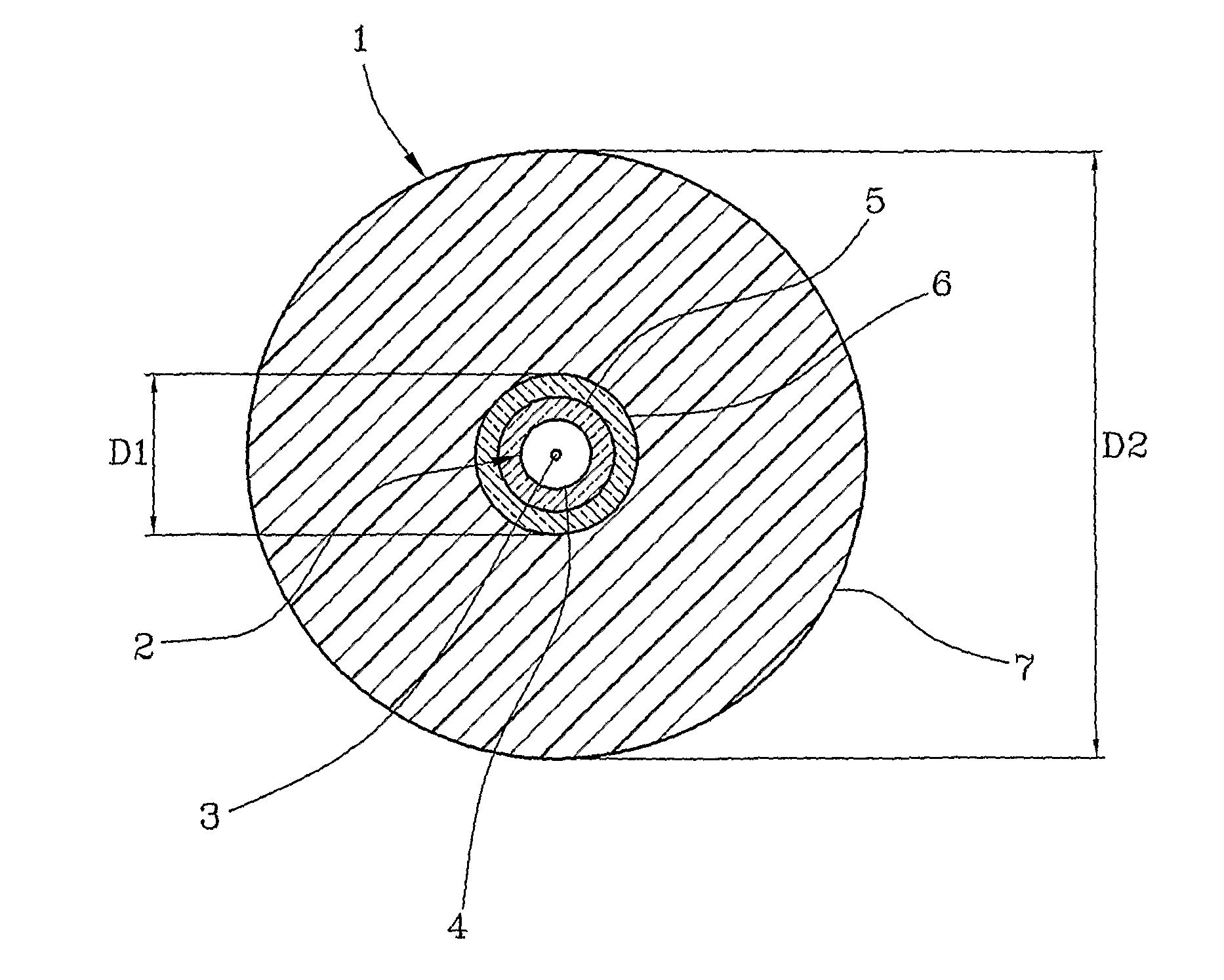
[0009]The Applicant has faced the problem of providing optical cables particularly suitable for riser and horizontal indoor installations, e.g. in multi-floor buildings, with the aim of reducing both field labour and required installation skill.
[0011]Moreover, when cabling a building, the optical fiber buffer layer needs to be congruent as much as possible to the optical fiber, preferably at a distance of about 100-150 cm from the stripping point (or less), in order to allow installation of an adjacent optical fiber in another recipient equipment (e.g. a termination box or the like), avoiding the risk that pulling movement on such adjacent fiber may disturb or otherwise affect the other fibers already connected or in the process of being connected.
[0012]The Applicant has now found that it is possible to install an optical fiber, extracted by a vertical cable (riser) within a building or the like, by providing a tight buffer protection to the optical fiber, in which said buffer has a combination of properties, including buffer-to-fiber clearance and mechanical strength of the buffer layer polymeric material, suitable to allow the stripping of a relatively low length of buffer, and to cause buffer-to-fiber congruence after a relatively short distance from the buffer end.
[0013]The above combination of features of the polymeric material forming the buffer layer allows to obtain an optical fiber which is effectively protected during the installation operations and during use, and at the same time can be easily stripped by the installer without using any stripping tools, simply by applying a small pressure with his fingertips and a moderate tearing force along the fiber axis. The stripping can be achieved in one pass, i.e. in a single stripping operation, for a length sufficient to have the optical fiber accessible for the subsequent jointing / splicing operations, for example from a few centimeters up to about 50 cm, without significant efforts. On the other hand, the tight configuration of the buffer layer ensures the desired congruence between optical fiber and buffer layer at a distance of about 100 cm from the end of the buffer layer. In other words, the optical fiber according to the invention is substantially unstrippable in one pass above a length of about 100 cm±30 cm.
[0019]It should be noted that the tight buffer layer of the present invention shall not be confused with a so called “buffer tube”. A buffer tube typically includes one or more optical fibers disposed within the same, possibly immersed in a water-blocking material (usually a grease) which inhibits migration of water which may penetrate into the buffer tube. Moreover, a buffer tube generally have a relatively large inner diameter when compared to the outer diameter of each optical fiber inserted therein, in order to allow the fiber to move freely thereinto.
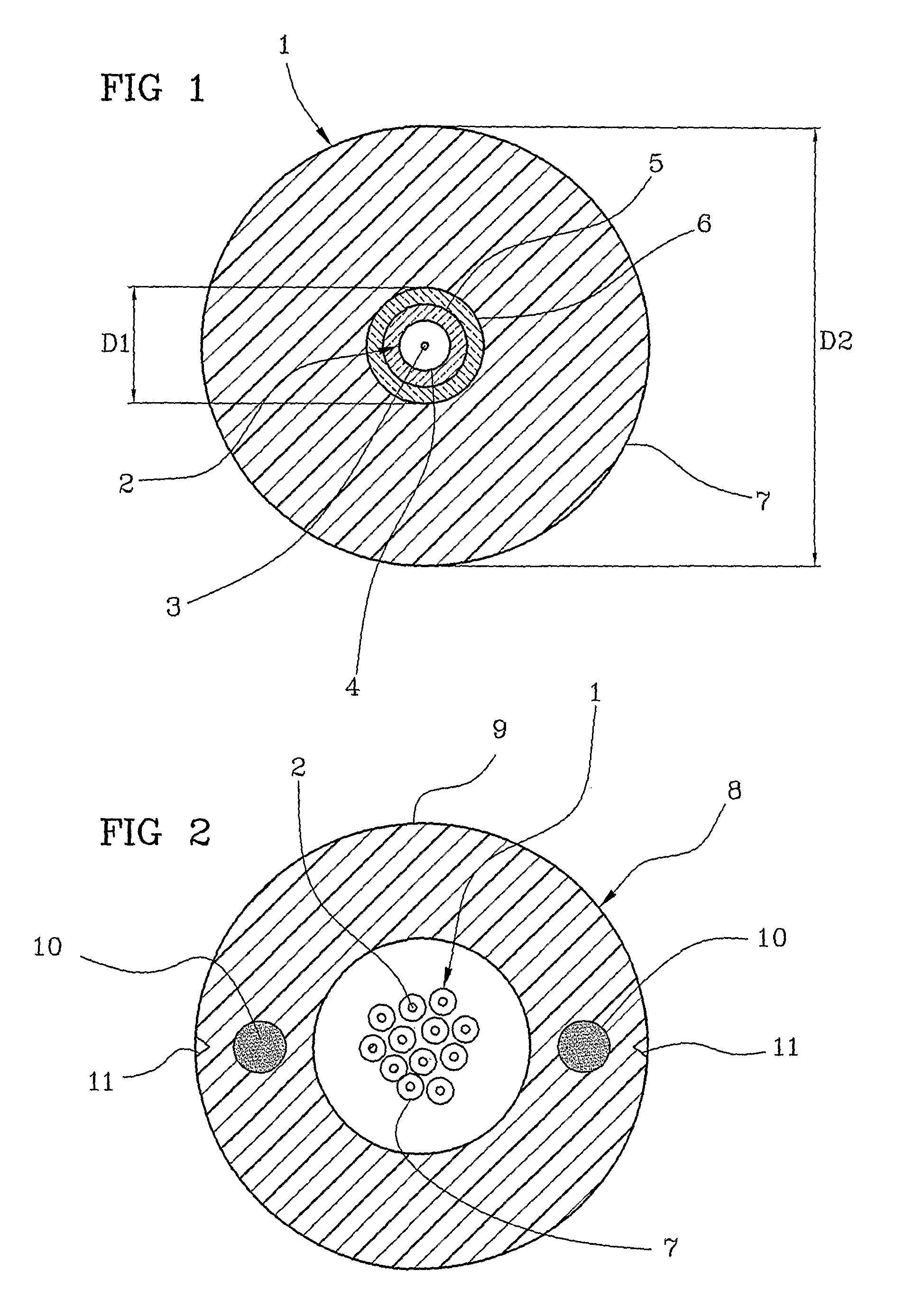
[0042]Preferably, at least one reinforcing element is embedded into the polymeric sheath and disposed along the length of the cable, so as to reduce mechanical stresses on the optical fibers due to tensile forces. Usually the reinforcing element is made from a glass reinforced polymer (GRP) rod or from an aramid rod.

Problems solved by technology

The forces exerted on the fiber during the extraction procedure can damage the optical fiber.
On the other hand, to carry out the connection of the optical fiber to the recipient equipment (e.g. a termination box or the like), the buffer layer shall be peeled off from the optical fiber, and when the buffer layer is tight the stripping of the due length is difficult and can require special tools and skilled installers.
Conversely, a loose buffer is easily strippable from the optical fiber, but it does not provide an adequate protection in an indoor cable system where a vertical position and the lack of adherence between optical fiber and buffer may cause tearing of the loose buffer and / or fiber microbending.

Method used


Image

  • Telecommunication cable equipped with tight-buffered optical fibers
  • Telecommunication cable equipped with tight-buffered optical fibers
  • Telecommunication cable equipped with tight-buffered optical fibers

Examples


example 1

Preparation of a Polymeric Composition

[0065]A polymeric composition were prepared by using the components as shown in Table 1 (the amounts are expressed as % by weight with respect to the total weight of the polymeric composition).

[0066]

TABLE 1Componentwt %Lotryl ® 17BA0730.2Lotryl ® 30BA027.1Clearflex ® CLB010.1Fusabond ® MC 250D3Hydrofy ® GS 1.547.2Rhodorsil ® GUM 9012Irganox ® 10100.4Lotryl ® 17BA07 (Atofina): copolymer ethylene-butyl acrylate containing 16% to 19% by weight of acrylic ester;Lotryl ® 30BA02 (Atofina): copolymer ethylene-butyl acrylate containing 28% to 32% by weight of acrylic ester;Clearflex ® CLB0 (Polimeri Europa): very low density polyethylene;Fusabond ® MC 250D (DuPont): ethylene-vinyl acetate (28% vinyl acetate);Hydrofy ® GS1.5 (Sima): magnesium hydroxide coated with stearic acid;Rhodorsil ® GUM 901 (Rhodia): dimethylsiloxane, methyl vinyl terminated gum;Irganox ® 1010 (Ciba Specialty Chemicals): phenolic antioxidant.

[0067]The composition were prepared by m...

example 2

Preparation of a Tight Buffer Optical Fiber

[0070]The polymeric composition as prepared in Example 1 was applied by extrusion onto an optical fiber having an overall diameter of 245±5 μm, with a primary coating having a thickness of 32.5 μm and a secondary coating having a thickness of 27.5 μm.

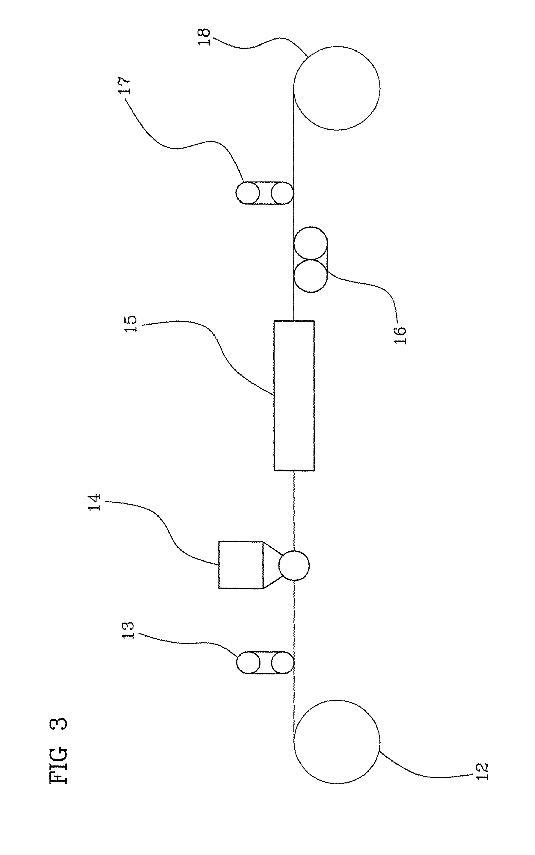
[0071]The operating conditions of the extruding line were the following:[0072]conic tip inner diameter: 0.45 mm;[0073]conic tip outer diameter: 0.90 mm;[0074]conic die inner diameter: 1.90 mm;[0075]vacuum: −0.1 bar[0076]line speed: 60 m / min;[0077]thermal profile: 125° C. (zone 1), 140° C. (zone 2), 150° C. (zone 3), 160° C. (collar), 165° C. (head);[0078]cooling trough: air at 25° C.;[0079]fibre pay off tension: 100 g[0080]buffered fibre take-up tension: 200 g

[0081]The so obtained buffered optical fiber had an external diameter of 900 μm.

[0082]The following measurements were made on the buffered optical fiber (mean values calculated from nine tested samples):[0083]average strip force: 0.22 N / 15...

example 3

Manual Stripping Test

[0094]Five buffered optical fibers according to the invention coming from different production batches were employed for the test. The buffer layers were manually stripped-off the fibers by the same operator at increasing lengths starting from 10 cm. All of the five optical fibers were easily deprived of the buffer thereof until a length of 50 cm. At a length of 90 cm the buffer of two optical fibers could not be stripped off. For the remaining three, the coherence between buffer and optical fiber (impeding the buffer stripping-off) was reached at 120 cm (two fibers) and 130 cm (one fiber).


PUM

PropertyMeasurementUnit
ultimate tensile strengthaaaaaaaaaa
ultimate elongationaaaaaaaaaa
diameteraaaaaaaaaa

Abstract

A telecommunication cable is equipped with at least one optical fiber coated by a tight buffer layer made from a polymeric material having an ultimate elongation equal to or lower than 100% and an ultimate tensile strength equal to or lower than 10 MPa. The above combination of features of the polymeric material forming the buffer layer provides an optical fiber which is effectively protected during installation operations and during use, and at the same time can be easily stripped by an installer without using any stripping tools, simply by applying a small pressure with his fingertips and a moderate tearing force along the fiber axis.

Description

CROSS REFERENCE TO RELATED APPLICATION[0001]This application is a national phase application based on PCT / IB2007 / 002187, filed Jul. 30, 2007, the content of which is incorporated herein by reference.BACKGROUND OF THE INVENTION[0002]The present invention relates to a telecommunication cable equipped with at least one optical fiber. In particular, the present invention relates to a telecommunication cable equipped with at least one tight-buffered optical fiber, especially suitable for indoor installations.[0003]An optical fibre generally comprises a core surrounded by a cladding, said core and cladding being preferably made of glass, and at least one coating. The combination of core and cladding is usually identified as “optical waveguide”. Usually, the coatings of the optical waveguide are two. The coating directly contacting the optical waveguide is called “first coating” or “primary coating”, and the coating overlying the first one is called “second coating” or “secondary coating”....

Claims


Application Information

Patent Timeline
Patent Type & Authority Patents(United States)
IPC IPC(8): G02B6/44G02B6/02
CPCC08L23/0869G02B6/4429C08L23/0853C08L2203/20C08L2203/202C08L2205/02C08L2205/03G02B6/443G02B6/4402C08L2666/02
Inventor CONSONNI, ENRICOCESCHIAT, DAVIDE
Owner PRYSMIAN SPA
Learn More