Continuous microseismic mapping for real-time 3D event detection and location

a technology of microseismic mapping and event detection, applied in seismology for waterlogging, instruments, measurement devices, etc., can solve the problems of inability to realize real-time operation, unstable and unreliable steps, and inability to accurately locate the even

Inactive Publication Date: 2013-07-23
SCHLUMBERGER TECH CORP
View PDF21 Cites 4 Cited by
  • Summary
  • Abstract
  • Description
  • Claims
  • Application Information

AI Technical Summary

Problems solved by technology

These approaches have been applied to individual sensor channels and hence have tended to be unstable and unreliable in the presence of significant noise.
Accordingly, intervention, pick verification, and manual pick adjustment have often been required, but those steps are time consuming and do not permit real-time operation.
However, the CMM technique as described above has some inherent drawbacks, including that it has not provided standard measures of localization uncertainty which in the past have been computed from the measurement versus model residuals associated with discrete time picks, and that the assumed geometries cause the accuracy of the above approach to break down as wellbore deviation increases and events move away from the target plane.
The CMM technique may also encounter drawbacks for multi-well data acquisition, where the ability to handle an arbitrarily distributed receiver network is preferred.

Method used


Image

  • Continuous microseismic mapping for real-time 3D event detection and location
  • Continuous microseismic mapping for real-time 3D event detection and location
  • Continuous microseismic mapping for real-time 3D event detection and location

Examples


Embodiment Construction

[0026]So that the above recited features and advantages of the present invention can be understood in detail, a more particular description of the invention, briefly summarized above, may be had by reference to the embodiments thereof that are illustrated in the accompanied drawings and graphs. It is to be noted, however, that the drawings illustrate only typical embodiments of this invention and are therefore not to be considered limiting of its scope, for the invention may admit to other equally effective embodiments.

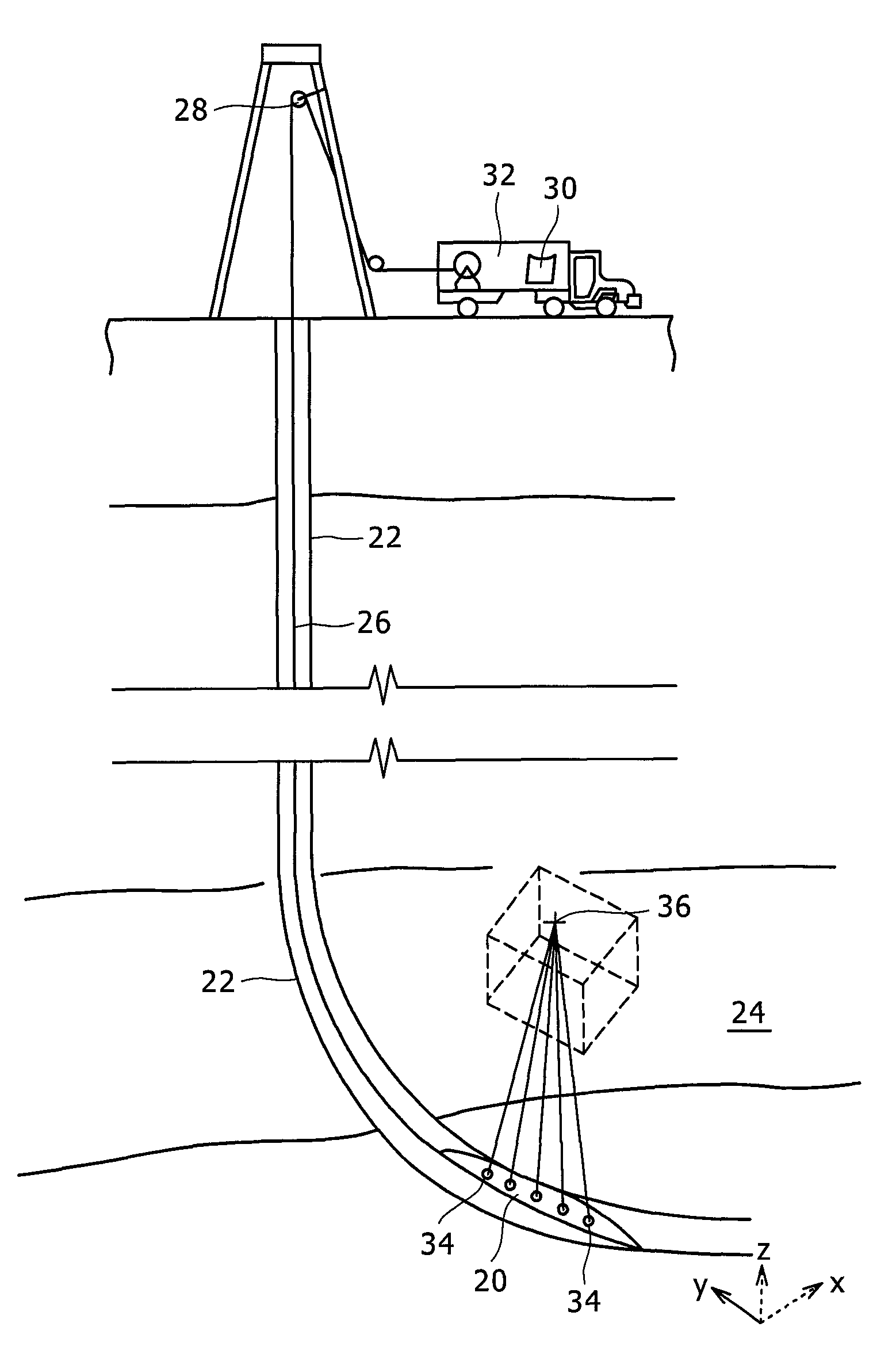
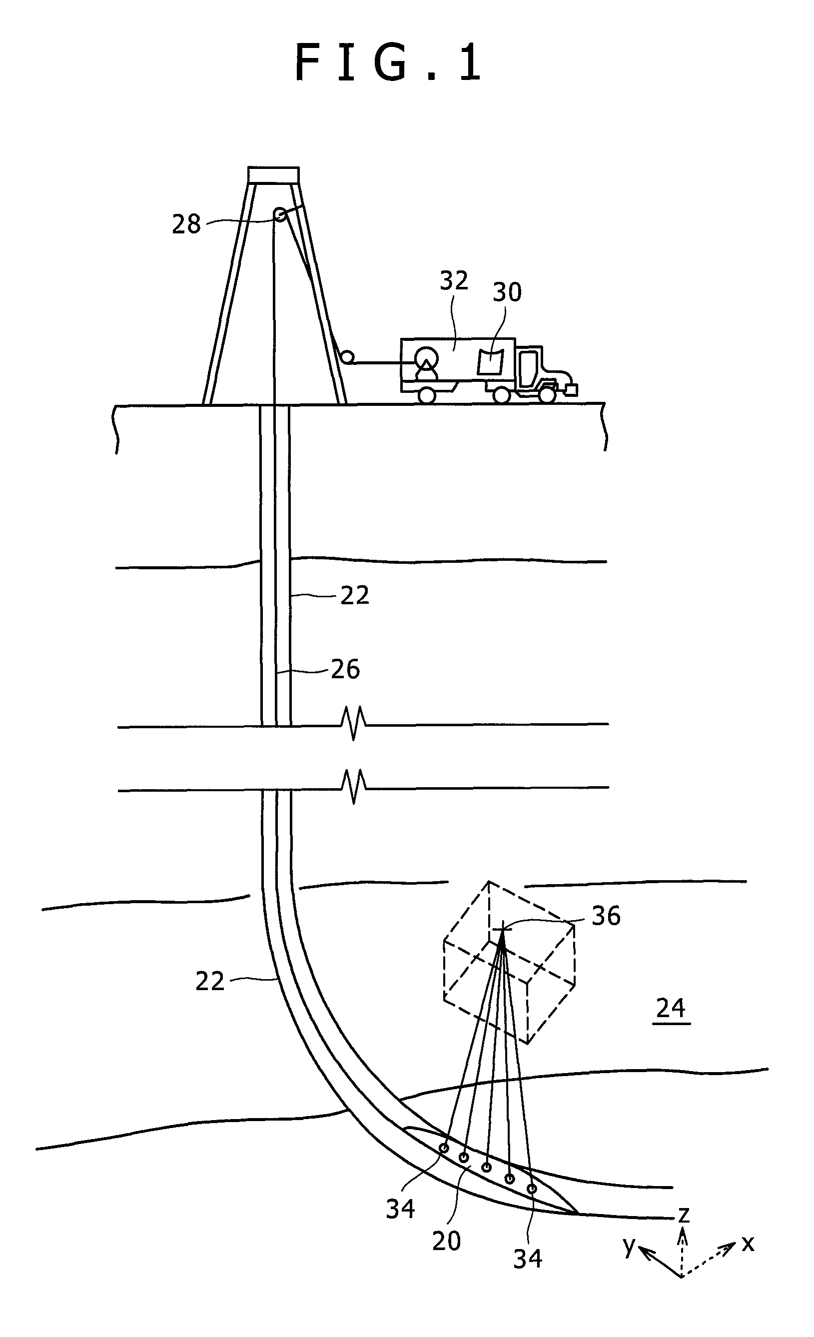
[0027]FIG. 1 is a schematic illustration of one exemplary embodiment and one exemplary method of deployment, showing a system including a downhole tool that may be used in conjunction with the methods described herein. The system of FIG. 1 depicts a seismic tool 20 disposed in a borehole 22 adjacent a formation of interest 24. The tool 20 may be deployed using conventional logging cable 26, or by another method of deployment that is consistent with the principles desc...


PUM


Abstract

A method for the detection and localization of microseismic events is proposed which operates in real-time. It provides hypocenters in three spatial dimensions along with an estimate of the event origin time. Sensor positions may be distributed in 3D space, and are not confined to linear arrays in vertical wells. The method combines and improves two existing approaches. For detection and localization purposes the method makes use of the generalized beam-forming and forward modeling properties defined in the “CMM” algorithm. For location refinement, the method uses a stabilized version of the generalized “Geiger” approach.

Description

CROSS REFERENCE TO RELATED APPLICATIONS[0001]This application is a non-provisional application of U.S. Provisional Patent Application 61 / 043,709, filed 9 Apr. 2008, the content of which is incorporated herein by reference for all purposes.BACKGROUND OF THE DISCLOSURE[0002]1. Field of the Invention[0003]The present disclosure relates to methods and techniques for continuous microseismic mapping and, more particularly, methods and techniques for the real-time 3d detection of microseismic events usable in non-vertical boreholes.[0004]2. Background of the Related Art[0005]A reliable real-time scheme for the detection / localization of microseismic events is important for Hydraulic Fracture Monitoring (HFM) and Reservoir Monitoring (RM), to enable timely decision making during stimulation operations and for reservoir management, among other applications. Microseismic event detection, location estimation and source parameter analysis provide critical information on the position, extent and ...

Claims


Application Information

Patent Timeline
Patent Type & Authority Patents(United States)
IPC IPC(8): G01V1/00G01V1/28
CPCG01V1/288G01V2210/123G01V2210/1429G01V1/40
Inventor KHADHRAOUI, BASSEMLESLIE, HAROLD DAVIDMICHAUD, GWENOLALEANEY, W. SCOTT
Owner SCHLUMBERGER TECH CORP
Why Eureka
Try Eureka