Magnetic head for perpendicular magnetic recording having a main pole and a shield
a perpendicular magnetic and magnetic recording technology, applied in the direction of data recording, head winding construction, instruments, etc., can solve the problems of shortening the magnetic force produced, hindering the main pole from producing a write magnetic field of sufficient magnitude, and unable to allow the main pole to operate. , to achieve the effect of reducing the length of the magnetic path
- Summary
- Abstract
- Description
- Claims
- Application Information
AI Technical Summary
Benefits of technology
Problems solved by technology
Method used
Image

Examples
first embodiment
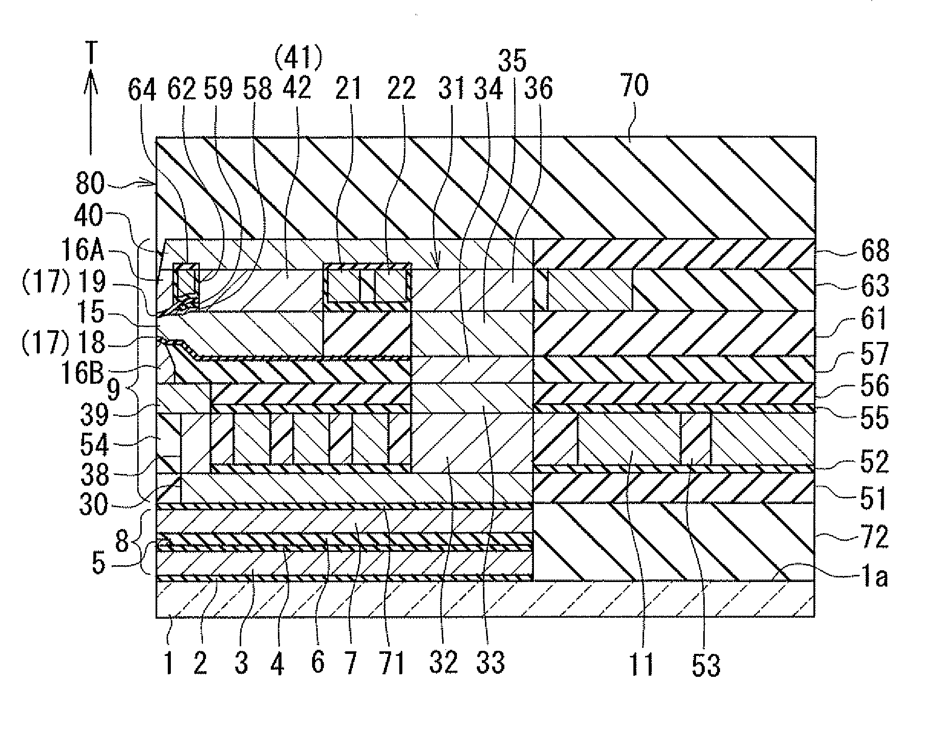
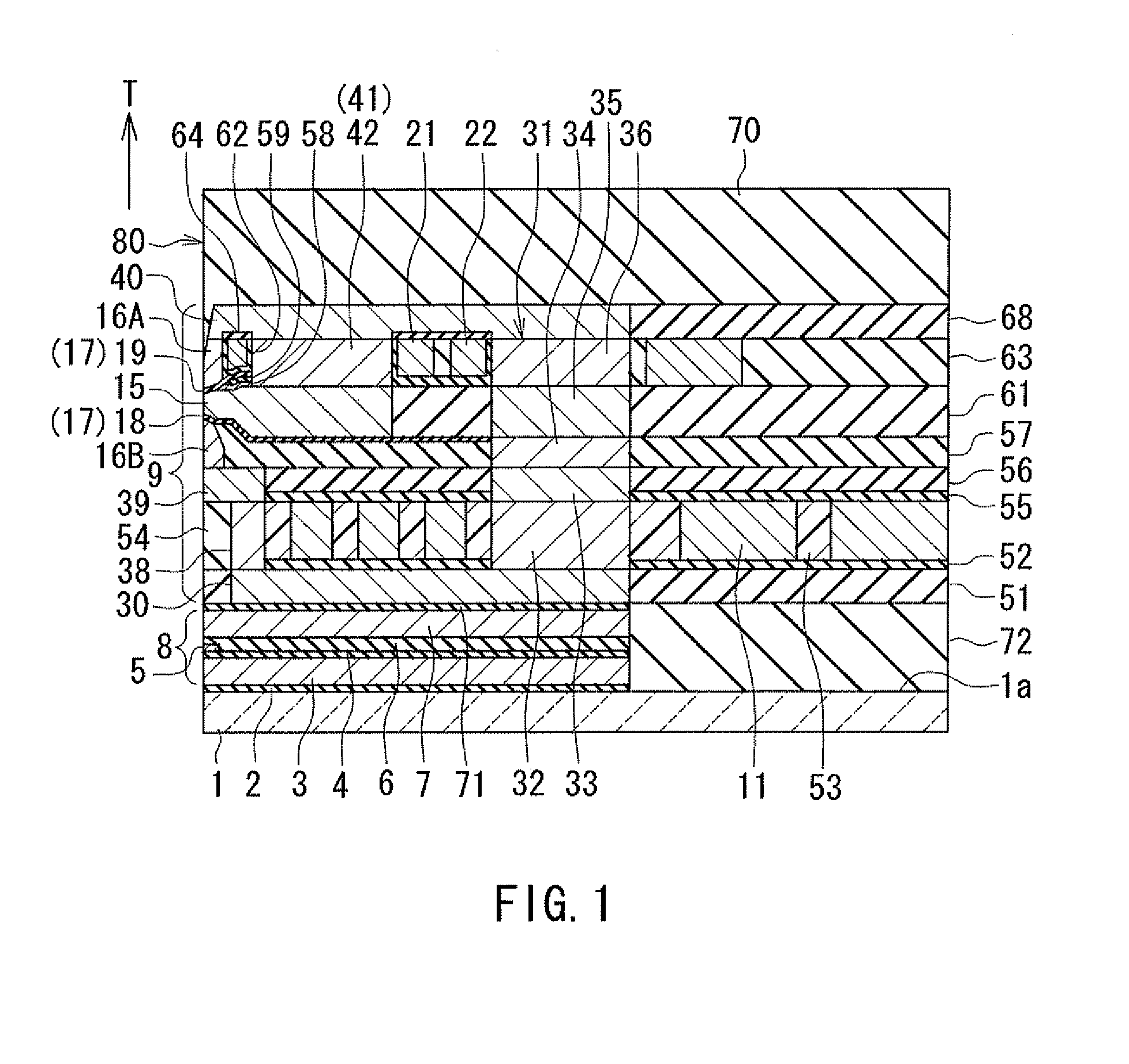
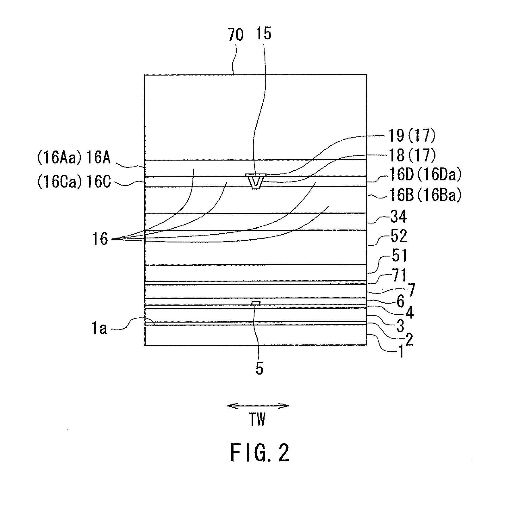
[0046]Embodiments of the present invention will now be described in detail with reference to the drawings. First, reference is made to FIG. 1 to FIG. 4 to describe the configuration of a magnetic head according to a first embodiment of the invention. FIG. 1 is a cross-sectional view of the magnetic head according to the present embodiment. In FIG. 1, the arrow with the symbol T indicates the direction of travel of a recording medium. FIG. 2 is a front view showing the medium facing surface of the magnetic head according to the present embodiment. FIG. 3 is a plan view showing a second coil of the magnetic head according to the present embodiment. FIG. 4 is a plan view showing first and third coils of the magnetic head according to the present embodiment. The arrows with the symbol TW in FIG. 2 to FIG. 4 indicate track width direction.
[0047]As shown in FIG. 1 and FIG. 2, the magnetic head for perpendicular magnetic recording (hereinafter simply referred to as the magnetic head) accor...
second embodiment
[0111]A magnetic head according to a second embodiment of the invention will now be described with reference to FIG. 5 to FIG. 8. FIG. 5 is a cross-sectional view of the magnetic head according to the present embodiment. Note that FIG. 5 shows the main cross section. FIG. 6 is a plan view showing a second coil of the magnetic head according to the present embodiment. FIG. 7 is a plan view showing a third coil of the magnetic head according to the present embodiment. FIG. 8 is a plan view showing a first coil of the magnetic head according to the present embodiment.
[0112]The magnetic head according to the present embodiment is different from the magnetic head according to the first embodiment in the following respects. In the present embodiment, the write head section 9 has a first coil 23 and a third coil 24 in place of the first coil 21 and the third coil 22 of the first embodiment. Here, assume a virtual plane that intersects the end face of the main pole 15 located in the medium ...
third embodiment
[0119]A magnetic head according to a third embodiment of the invention will now be described with reference to FIG. 9 to FIG. 11. FIG. 9 is a cross-sectional view of the magnetic head according to the present embodiment. Note that FIG. 9 shows the main cross section. FIG. 10 is a plan view showing a third coil of the magnetic head according to the present embodiment. FIG. 11 is a plan view showing a first coil of the magnetic head according to the present embodiment.
[0120]The magnetic head according to the present embodiment is different from the magnetic head according to the second embodiment in the following respects. In the present embodiment, the write head section 9 has a third coil 25 in place of the third coil 24 of the second embodiment. The third coil 25 is made of a conductive material such as copper.
[0121]The positional relationship of the third coil 25 with the main pole 15 and the second coupling part 31 (the magnetic layer 35) is the same as that of the third coil 24 ...
PUM
| Property | Measurement | Unit |
|---|---|---|
| thickness | aaaaa | aaaaa |
| thickness | aaaaa | aaaaa |
| height | aaaaa | aaaaa |
Abstract
Description
Claims
Application Information
 - R&D
- Intellectual Property
- Life Sciences
- Materials
- Tech Scout
- Unparalleled Data Quality
- Higher Quality Content
- 60% Fewer Hallucinations
Browse by: Latest US Patents, China's latest patents, Technical Efficacy Thesaurus, Application Domain, Technology Topic, Popular Technical Reports.
© 2025 PatSnap. All rights reserved.Legal|Privacy policy|Modern Slavery Act Transparency Statement|Sitemap|About US| Contact US: help@patsnap.com