Power supply system for crane

a technology of power supply system and gantry crane, which is applied in the direction of cable arrangement between relatively moving parts, transportation and packaging, and arrangement using take-up reel/drum, etc. it can solve problems such as safety and operability in attaching and detaching operations, and achieve the effects of reducing trouble risk, preventing derailment and turnover accidents, and simplifying the operation of linking and unlinking the linkage mechanism for lane chang

Inactive Publication Date: 2013-08-06
MITSUI E&S MACHINERY CO LTD
View PDF16 Cites 8 Cited by
  • Summary
  • Abstract
  • Description
  • Claims
  • Application Information

AI Technical Summary

Benefits of technology

[0021]According to the power supply system for a crane according to the present invention, the linkage mechanism connecting the crane and the power supply truck is configured not to transmit any force of the crane in the transverse direction or the twisting direction to the power supply truck. This configuration can prevent derailment and turnover accidents of the power supply truck. Accordingly, even a power supply truck including no driving system therein can stably follow the crane. Moreover, since the linkage mechanism has a simple configuration ob being formed of a rod or the like, the linkage mechanism is highly durable and can reduce risk of troubles.
[0022]Further, linking and unlinking operations of the linkage mechanism for lane change are simplified. This can shorten a time required for lane change.
[0023]Further, the configuration of connecting the power supply connector and the transformer with the power supply belt without using a cable reel, can lower the center of gravity of the power supply truck and prevent turnover accidents of the power supply truck. Moreover, the configuration of disposing the power supply cable in the articulated belt can protect the cable from being damaged, or the like.

Problems solved by technology

However, although one of the advantages of RTTs is to be capable of changing lanes easily, this is difficult in the case of using the above-described method.
Moreover, the power supply connectors 32 carry high-voltage electricity and have problems in safety and operability in attaching and detaching operations.

Method used


Image

  • Power supply system for crane
  • Power supply system for crane
  • Power supply system for crane

Examples


Embodiment Construction

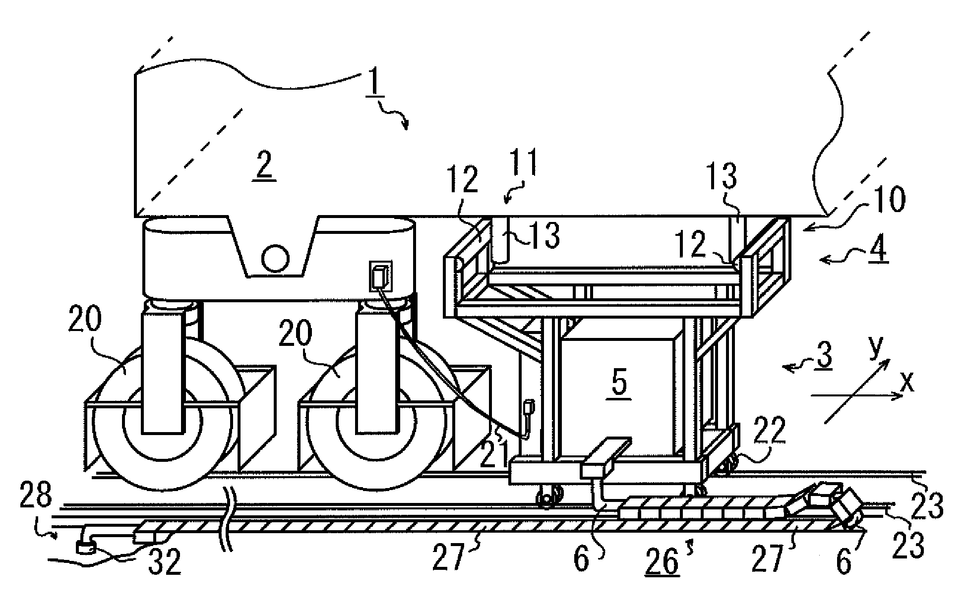
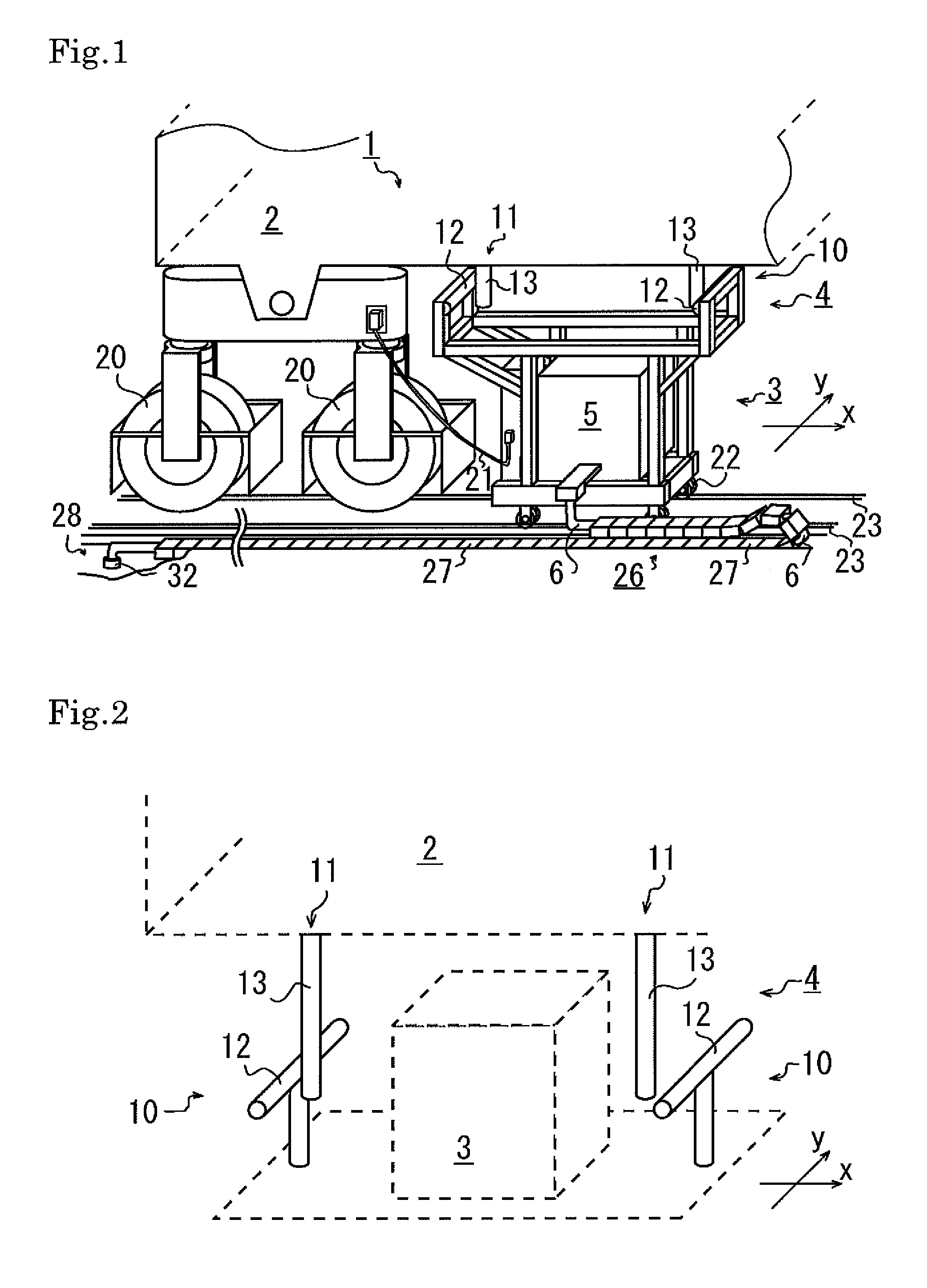
[0032]A power supply unit for a crane according to an embodiment of the present invention will be described below with reference to the drawings. FIG. 1 shows a crane 2 and a power supply truck 3 included in a power supply system 1. The power supply truck 3 is configured to supply power to the crane 2 through a connection part 21 while traveling by following a travel of the crane 2. A linkage mechanism 4 for the crane 2 and the power supply truck 3 includes a receiving member 10 disposed on the power supply truck 3 and a pushing member 11 disposed on the crane 2.

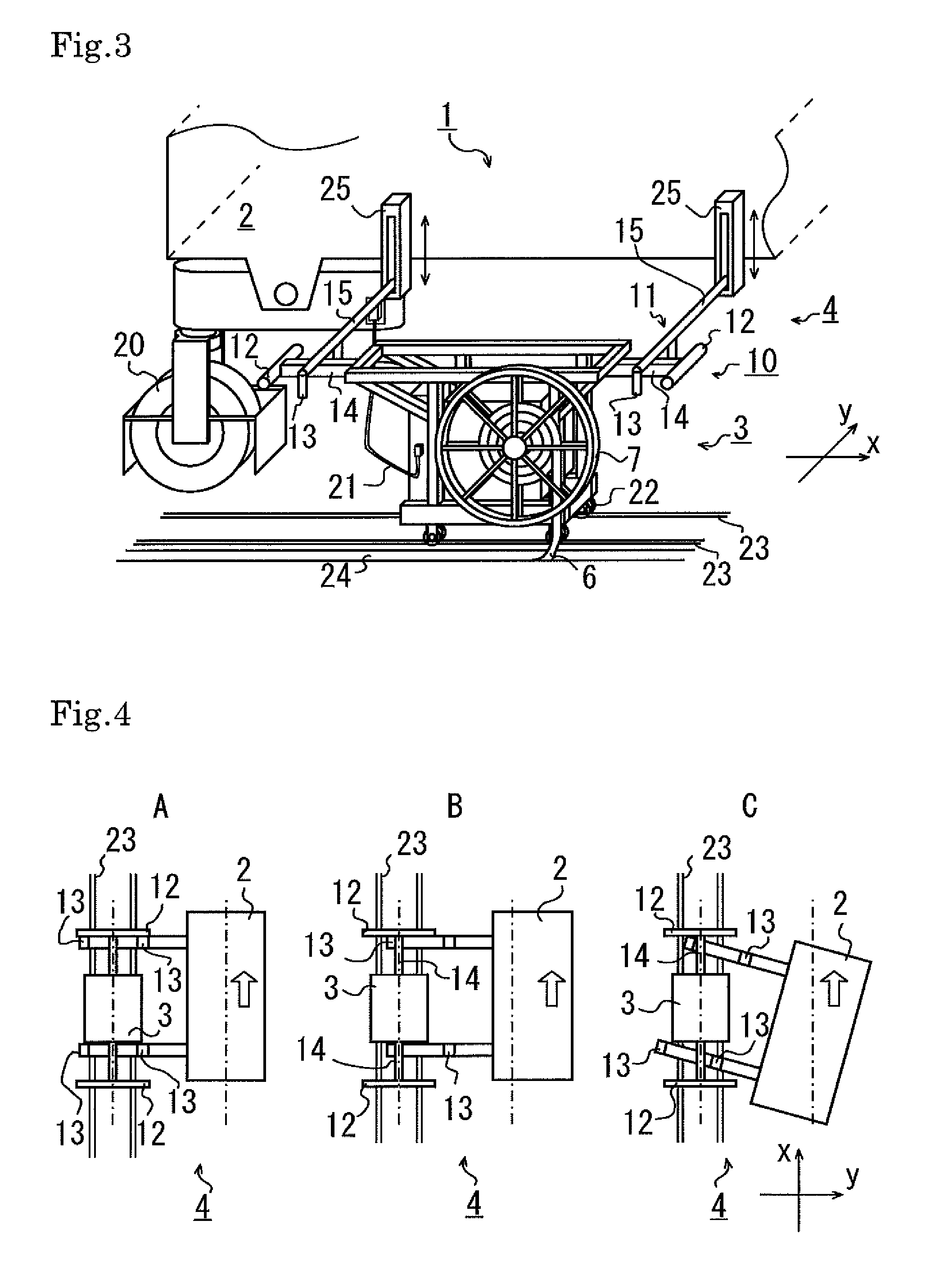
[0033]The receiving member 10 disposed on the power supply truck 3 includes two contact bars 12 each extending in a direction intersecting a travel direction x. Desirably, each of the contact bars 12 is arranged in a direction orthogonal to the travel direction x. The pushing member 11 disposed on the crane 2 includes two rods 13 arranged respectively on inner sides of the two contact bars 12.

[0034]Next, operation of the lin...


PUM


Abstract

Provided is a power supply system including a crane and a power supply truck. In the power supply system, a linkage mechanism efficiently transmits a force in a travel direction x to the power supply truck, while not transmitting any force in a transverse direction y or a twisting direction, and has a highly durable configuration. In a power supply system 1 for a crane in which a crane 2 for loading and unloading a container for marine transportation is linked to a power supply truck 3 for supplying power while following the crane 2, with a linkage mechanism 4, the linkage mechanism 4 includes a receiving member 10 disposed on the power supply truck 3, and a pushing member 11 disposed on the crane 2. The power supply system 1 includes the linkage mechanism 4 configured in a manner that, when the crane 2 moves in a travel direction x, the pushing member 11 comes into contact with the receiving member 10, to transmit a force of the crane 2 moving in the travel direction x to the power supply truck 3, and when the crane 2 moves in a transverse direction y intersecting the travel direction x, the receiving member 10 does not disturb move of the pushing member 11 and a force of the crane 2 moving in the transverse direction y is not transmitted to the power supply truck 3.

Description

CROSS-REFERENCE TO RELATED APPLICATIONS[0001]The present patent application is a nationalization of International application No. PCT / JP2010 / 053657, filed Mar. 5, 2010, published in Japanese, which is based on, and claims priority from, Japanese Application No. 2009-052185, filed Mar. 5, 2009, both of which are incorporated herein by reference in their entireties.TECHNICAL FIELD[0002]The present invention relates to a power supply system for a gantry crane used for loading and unloading containers at a harbor or inland container terminal, or the like.BACKGROUND ART[0003]At a container terminal in a harbor, an inland area or the like, quay cranes and gantry cranes are used to load and unload containers to and from ships and trailers.[0004]FIG. 6 is a schematic view of a harbor container terminal 30. A container 35 on a container ship 34 is loaded onto a trailer 33 by a quay crane 36, and is then loaded onto a lane 31, which is a container load block, from the trailer 33 by a gantry c...

Claims


Application Information

Patent Timeline
Patent Type & Authority Patents(United States)
IPC IPC(8): B66C13/12
CPCB66C13/12
Inventor ICHIMURA, KINYA
Owner MITSUI E&S MACHINERY CO LTD
Why Eureka
Try Eureka