
Scanner and weigh scale with self-centering surface

a scanner and weigh scale technology, applied in the field of optical code scanners with an integrated weigh scale, can solve the problems of achieve the effect of slowing down the process of weighing items and preventing the development of lower cost scales

Active Publication Date: 2013-08-06
NCR CORP
View PDF4 Cites 0 Cited by
  • Summary
  • Abstract
  • Description
  • Claims
  • Application Information

AI Technical Summary

Benefits of technology

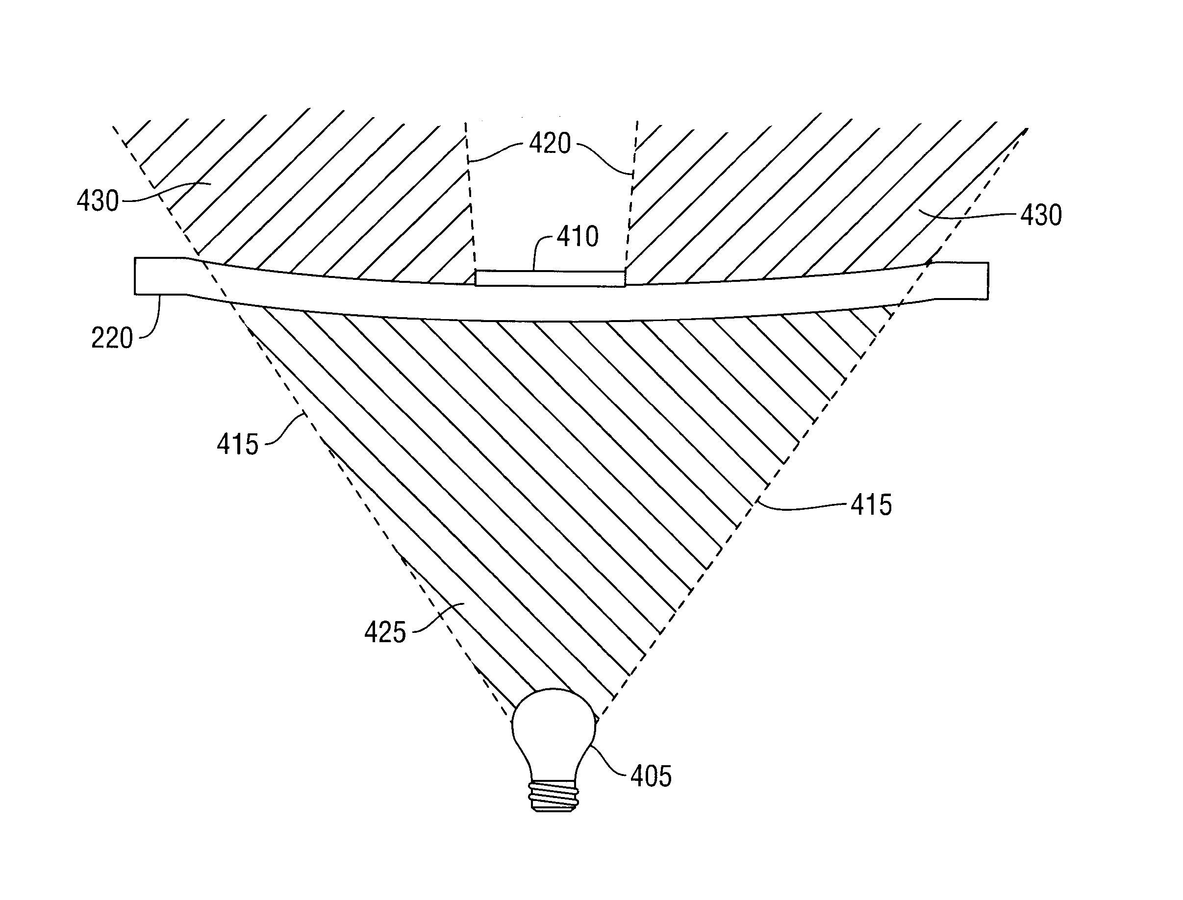
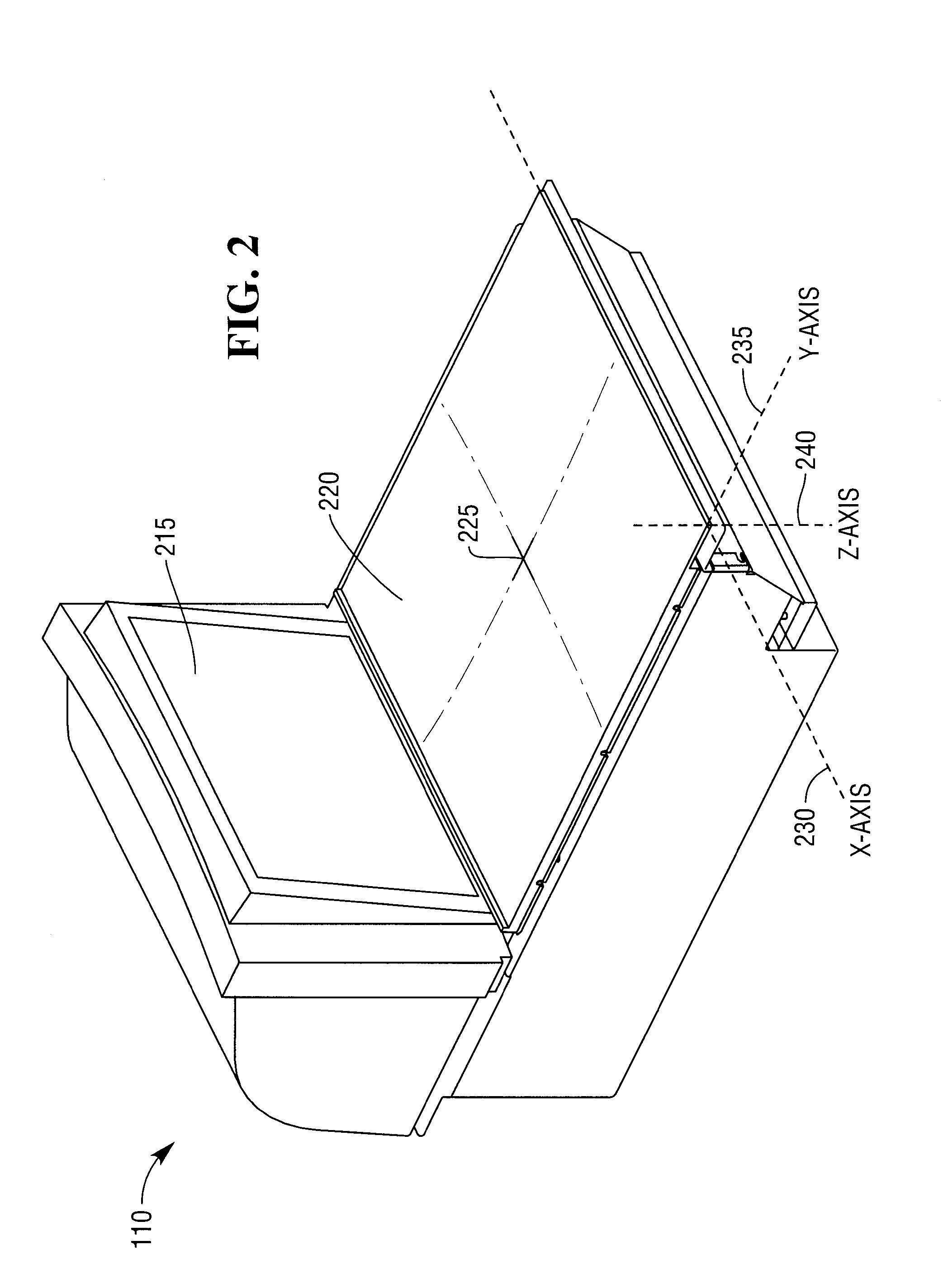
The present invention recognizes that the top plate of a weigh scale is a major cost component and items placed on it often roll off or remain in motion, preventing the development of a lower cost scale and slowing down the process of weighing items. The invention addresses this problem by removing the portion of the top plate that contains optically clear material and replacing it with a low cost durable material that can self-center items placed on the top plate, preventing them from rolling off and dampening their movement. The top plate also has a neutral color and finish to reduce specular reflections and improve the ability to identify an item placed on the top plate. Additionally, the low cost durable material of the top plate is translucent to light projected onto its under side, which helps to better define or silhouette the outline of items placed on the top plate for identification.

Problems solved by technology

These conditions prevent the development of lower cost scale and slow down the process of weighing items.

Method used


Image

  • Scanner and weigh scale with self-centering surface
  • Scanner and weigh scale with self-centering surface
  • Scanner and weigh scale with self-centering surface

Examples


Embodiment Construction

[0014]In the following description, numerous details and embodiments are set forth to provide an understanding of the claimed invention. However, it will be appreciated by those skilled in the art that various modifications to the described embodiments may be made without departing from the spirit and scope of the invention and that numerous variations or modifications from the described embodiments are possible. Throughout this specification, like numbered elements are used to describe the same parts throughout the various drawing figures referred to and described.

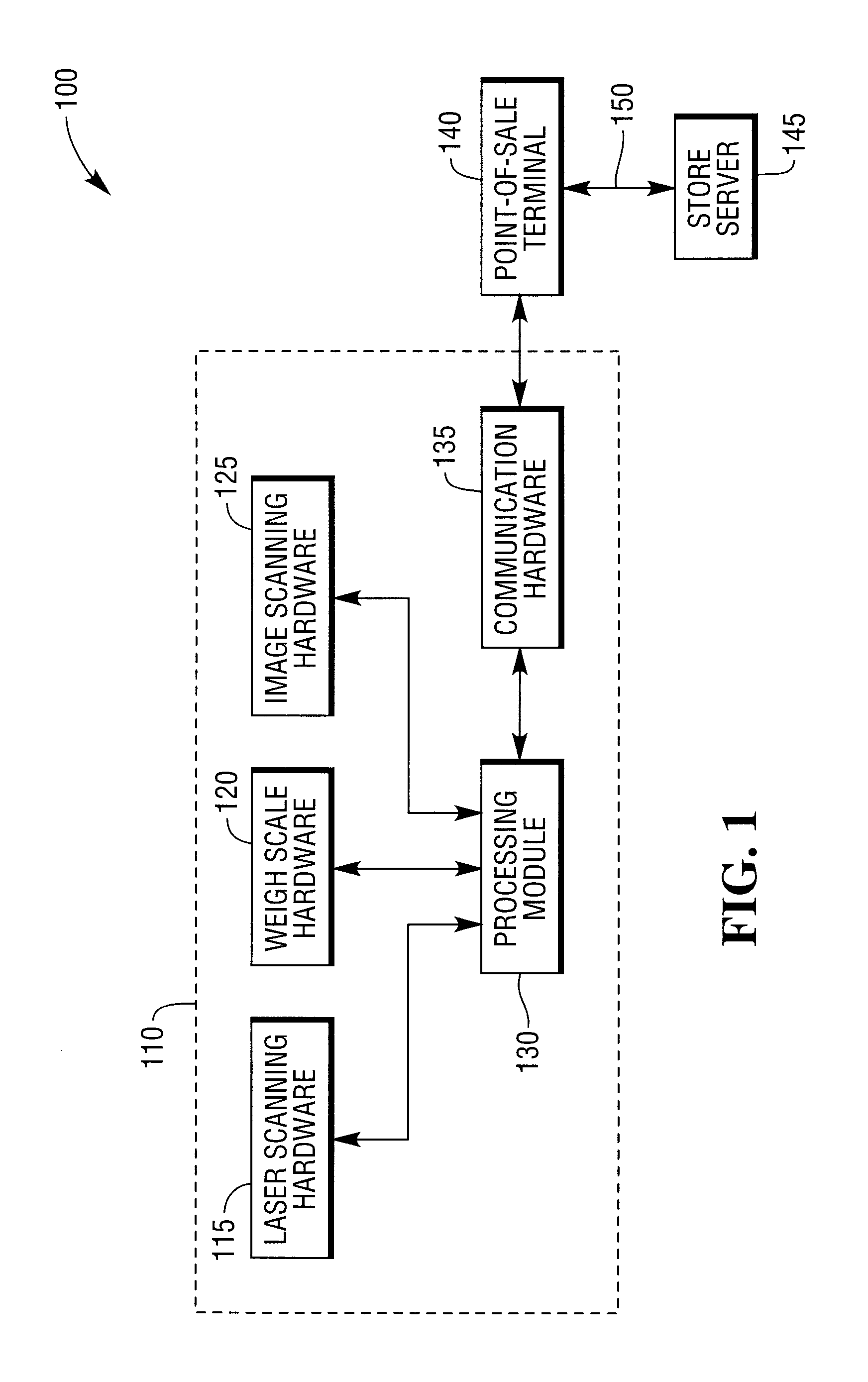
[0015]Referring to FIG. 1, there is provided a high-level block diagram illustrating an exemplar embodiment of an item scanner 110 in a retail environment 100. The retail environment 100 includes a store server 145 in communication with a point-of-sale (POS) terminal 140 over a network 150. A typical retail environment 100 has multiple POS terminals 140. The POS terminal 140 includes a number of devices and peripherals an...


PUM


Abstract

An optical scanner comprising a weigh scale is presented with a self-centering top plate. The design of the top plate creates a horizontal gravitation vector on objects placed on and away from the center of the top plate. The force vector is directed toward the center of the top plate and diminishes to zero as the object approaches the center of the top plate.

Description

FIELD OF THE INVENTION[0001]The present invention relates generally to optical code scanners. More particularly, but not exclusively, the invention relates to optical code scanners with an integrated weigh scale.BACKGROUND[0002]In a general retail environment where groceries are sold, it is common for a point-of-sale (POS) terminal to include an item scanning device and for the item scanning device to have an integrated item weigh scale. The item scanning device scans an item presented to the POS terminal and if an optical code is found, reads the optical code and communicates the information to the POS terminal. The weigh scale determines the weight of one or more items placed on the weigh scale's “top plate” or “weigh plate” as it is sometimes referred to.[0003]The top plate (horizontal surface) of a bi-optic item scanning device has a centered area composed of an optically transparent material to allow light, including laser light, to pass through. Whether the item scanning devic...

Claims


Application Information

Patent Timeline
Patent Type & Authority Patents(United States)
IPC IPC(8): G06K7/00
CPCG06K7/10722G06K7/10792
Inventor HERWIG, NATHANIEL CHRISTOPHER
Owner NCR CORP
Learn More