Stackable belleville spring

a technology of belleville springs and stacks, which is applied in the direction of ring springs, other domestic objects, transportation and packaging, etc., can solve the problems of premature failure of disc spring configurations and friction wear, and achieve the effect of avoiding friction wear and avoiding friction wear between the surfaces

Active Publication Date: 2013-08-06
TEMPER
View PDF39 Cites 13 Cited by
  • Summary
  • Abstract
  • Description
  • Claims
  • Application Information

AI Technical Summary

Benefits of technology

[0006]The present invention provides, in a second aspect, a disc spring stack which includes a first assembly. The first assembly includes generally conically-shaped disc springs that are stacked in parallel such that the conical adjacent surfaces of successive disc springs are spaced apart. The first assembly includes a first generally conically-shaped disc spring that has a first radial inner portion that defines a center hole therein, and a first radial outer portion. The first radial inner portion has a downwardly-depending portion and the first radial outer portion has an upwardly-extending portion. The first disc spring has a first intermediate portion which deflects under axial load. The first assembly also includes a second generally conically-shaped disc spring that has a second radial inner portion that defines a center hole therein, and a second radial outer portion. The second radial inner portion has a downwardly-depending portion, and the second radial outer portion has an upwardly-extending portion. The second disc spring has a second intermediate portion which deflects under axial load. In the first assembly, the second disc spring is stacked in parallel on the first disc spring such that the upwardly-extending portion of the first radial outer portion of the first disc spring is received on the second radial outer portion of the second disc spring. Further, when stacked, the downwardly-depending portion of the second radial inner portion of the second disc spring is received on the first radial inner portion of the first disc spring. As a result, the first intermediate portion of the first disc spring and the second intermediate portion of the second disc spring deflect under axial load while maintaining a space therebetween so as to avoid friction between the surfaces and resulting hysteresis that can be avoided by separating the parallel surfaces.
[0007]The present invention provides, in a third aspect, a disc spring stack which includes a first assembly, as described above, and a second assembly. The second assembly includes a third generally conically-shaped disc spring that has a first radial inner portion that defines a center hole therein, and a first radial outer portion. The first radial inner portion has an upwardly-extending portion and the first radial outer portion has a downwardly-depending portion. The third disc spring has a first intermediate portion which deflects under axial load. The second assembly also includes a fourth generally conically-shaped disc spring that has a second radial inner portion that defines a center hole therein, and a second radial outer portion. The second radial inner portion has an upwardly-extending portion, and the second radial outer portion has a downwardly-depending portion. The fourth disc spring has a second intermediate portion which deflects under axial load. In the second assembly, the fourth disc spring is stacked in parallel on the third disc spring. Therefore, the upwardly-extending portion of the first radial inner portion of the third disc spring is received on the second radial inner portion of the fourth disc spring and the downwardly-depending portion of the second radial outer portion of the fourth disc spring is received on the first radial outer portion of the third disc spring so that the first intermediate portion of the third disc spring and the second intermediate portion of the fourth disc spring deflect under axial load while maintaining a space therebetween so as to avoid friction wear.
[0011]The present invention provides, in a seventh aspect, a method of making a disc spring stack that includes a first assembly of generally conically-shaped disc springs that are stacked in parallel such that the conical adjacent surfaces of successive disc springs are spaced apart. This method includes obtaining a first generally conically-shaped disc spring that has a first radial inner portion defining a center hole therein and a first radial outer portion. The first radial inner portion has a downwardly-depending portion and the first radial outer portion has an upwardly-extending portion. The first disc spring has a first intermediate portion which deflects under axial load. Next, a second generally conically-shaped disc spring is obtained, which has a second radial inner portion defining a center hole therein and a second radial outer portion. The second radial inner portion has a downwardly-depending portion, and the second radial outer portion has an upwardly-extending portion. The second disc spring has a second intermediate portion which deflects under axial load. Next, the second disc spring is stacked in parallel on the first disc spring, such that the upwardly-extending portion of the first radial outer portion of the first disc spring is received on the second radial outer portion of the second disc spring. As a result of this method, the downwardly-depending portion of the second radial inner portion of the second disc spring is received on the first radial inner portion of the first disc spring, so as to allow the first intermediate portion of the first disc spring and the second intermediate portion of the second disc spring to deflect under axial load while maintaining a space therebetween so as to avoid friction wear.

Problems solved by technology

A problem with stacking a plurality of disc springs, particularly, when stacking in parallel, is the need to maintain the plurality of disc springs in the stack when a force is applied axially on the stack.
Furthermore, when such a force is applied axially to a parallel spring stack, the adjacent surfaces of the disc springs may rub against each other, causing friction wear.
This friction wear is often the cause of premature failure of disc spring configurations.

Method used


Image

  • Stackable belleville spring
  • Stackable belleville spring
  • Stackable belleville spring

Examples


Embodiment Construction

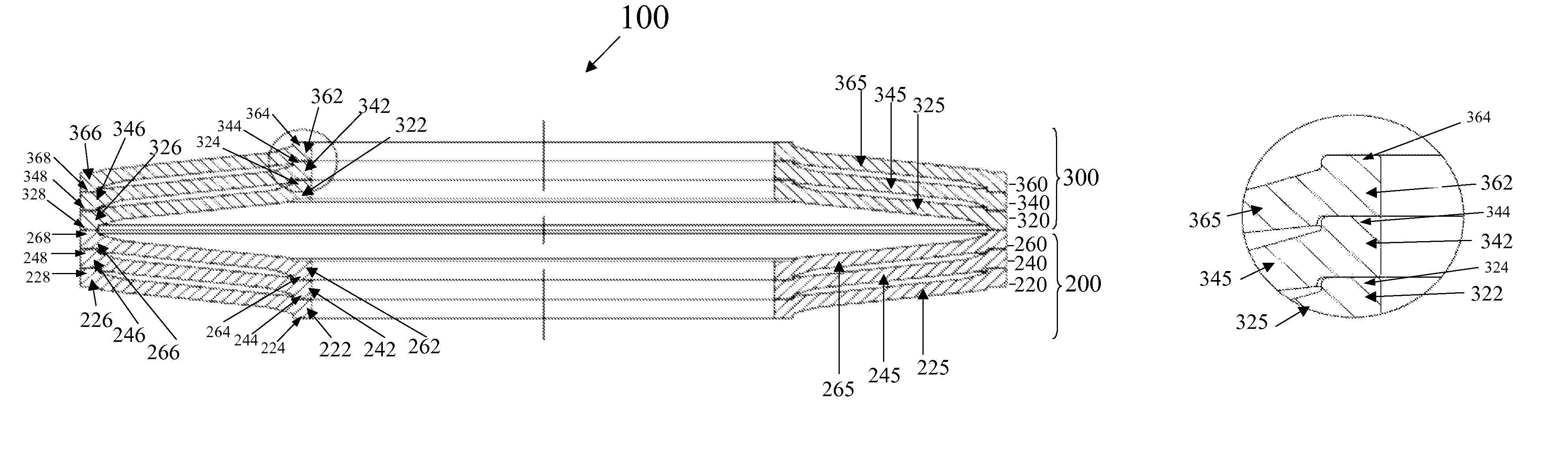
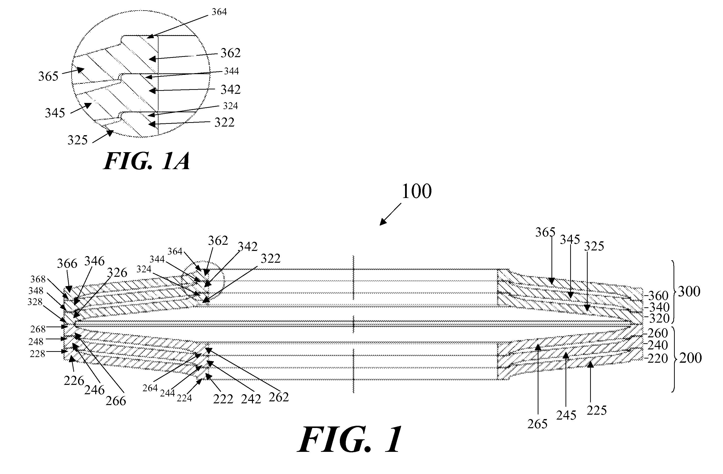
[0020]The disc springs and disc spring stacks of the present invention include a plurality of generally conically-shaped disc springs in which adjacent disc springs fit together and are held together in axial alignment. The disc spring stacks generally comprise a ring-shaped configuration and include an outer peripheral edge, which may be positioned within a cylindrically-shaped cavity or tube (not shown), and an inner edge, which may be positioned about a shaft or aligning rod (not shown). The disc springs may optionally be interlocking, which feature would allow the assemblies to be used without any confining cylinder or shaft in order to hold the disc springs in alignment, particularly under an axial load applied to the disc spring stack.

[0021]FIG. 1 illustrates a disc spring stack 100, in accordance with the present invention, having a first assembly 200, and a second assembly 300, with said assemblies stacked in series with one another. In general, stacking assemblies of disk s...


PUM

PropertyMeasurementUnit
friction wearaaaaaaaaaa
forceaaaaaaaaaa
frictionaaaaaaaaaa

Abstract

Disc springs that are resistant to premature failure caused by friction wear, disc spring assemblies and disc spring stacks including the disc springs, and methods of making and using said assemblies and stacks are disclosed.

Description

FIELD OF THE INVENTION[0001]The invention relates generally to disc springs and disc spring stacks that are resistant to friction wear.BACKGROUND OF THE INVENTION[0002]Disc springs, sometimes referred to as Belleville washers or Belleville springs, are conical shaped washers which are designed to be loaded in an axial direction. Under high loads disc springs produce small deflections, as compared with other types of springs such as helical or coil springs.[0003]Variable spring characteristics can be achieved by stacking a plurality of disc springs. A problem with stacking a plurality of disc springs, particularly, when stacking in parallel, is the need to maintain the plurality of disc springs in the stack when a force is applied axially on the stack. Furthermore, when such a force is applied axially to a parallel spring stack, the adjacent surfaces of the disc springs may rub against each other, causing friction wear. This friction wear is often the cause of premature failure of di...

Claims


Application Information

Patent Timeline
Patent Type & Authority Patents(United States)
IPC IPC(8): F16F1/34
CPCF16F1/32Y10T29/49609
Inventor RODE, JOHN E.
Owner TEMPER
Why Eureka
Try Eureka