Hydraulic unit for slip-controlled braking systems

a technology of hydraulic unit and braking system, which is applied in the direction of braking system, positive displacement liquid engine, liquid fuel engine, etc., can solve the problems of correspondingly high cost and complexity of drilling technology, less spatial economic positioning of remaining components, and difficulty in adjusting the braking system. , to achieve the effect of compact construction, complexity and cost of drilling, and further reduction of complexity

Active Publication Date: 2013-08-06
CONTINENTAL TEVES AG & CO OHG
View PDF18 Cites 60 Cited by
  • Summary
  • Abstract
  • Description
  • Claims
  • Application Information

AI Technical Summary

Benefits of technology

[0007]It is an object of the present invention to make available a hydraulic unit with a multi-piston pump which avoids the disadvantages of the prior art and makes possible an improved compromise for a drilling configuration.
[0008]The configuration proposed according to aspects of the invention consists substantially in arranging the relatively large-volume receiving bores for the pumping devices in respective V-shaped pairs at an angle to one another within three imaginary horizontal planes E1, E2, E3. Because the pumping devices are positioned within these horizontal planes E1-E3 to some extent in a stratified manner, but with only a relatively small offset from a common vertical plane V1, relatively extensive zones without receiving bores for pumping devices are produced in the receiving body, which to a large extent can be utilized entirely—without regard to the pumping devices—for arranging other components therein. Furthermore, a configuration bundled in this way makes possible a simplified drilling process together with a more compact construction.
[0011]Dimensional control as well as programming of production machines is simplified if the drilling pattern of the receiving body is configured substantially symmetrically with respect to an imaginary vertical plane. The same is true in principle if the distances between the different horizontal planes are selected equally.
[0012]The number of chucking and rechucking operations is reduced if the receiving bores for the pumping devices of a hydraulic circuit each start uniformly from one side of the receiving body.
[0014]Very generally, each plane or section plane has two receiving bores, the receiving bores being arranged in each case in a V-formation at an angle to one another, the included angle being greater than 90° and not more than 180°. If the plane containing the receiving bore which is offset at an acute angle is arranged between the section planes of the receiving bores positioned congruently in a vertical direction, this makes possible an especially space-saving, compact construction.
[0015]The complexity and cost of drilling are further reduced if receiving bores for valves are arranged substantially perpendicularly above the receiving bores for pumping devices, so that, for a bundled group of pumping devices on the suction side, there are provided substantially linear, vertical channel sections which, starting from these valve receiving bores, enter the receiving body perpendicularly and open into the receiving bores of the pumping devices.

Problems solved by technology

Although this has the advantage in principle that only two receiving bores for pumping devices are not disposed parallel to a vertical or horizontal of the receiving body, nevertheless such prioritized treatment of the receiving bores for the pumping devices produces a spatially less economical positioning of the remaining components.
This way of proceeding suffers, to a degree, from the disadvantage that all the other components, with their associated connecting channels, must be designed around the receiving bores of the pumping devices.
This gives rise to correspondingly high cost and complexity of the drilling technology.

Method used


Image

  • Hydraulic unit for slip-controlled braking systems
  • Hydraulic unit for slip-controlled braking systems
  • Hydraulic unit for slip-controlled braking systems

Examples


Embodiment Construction

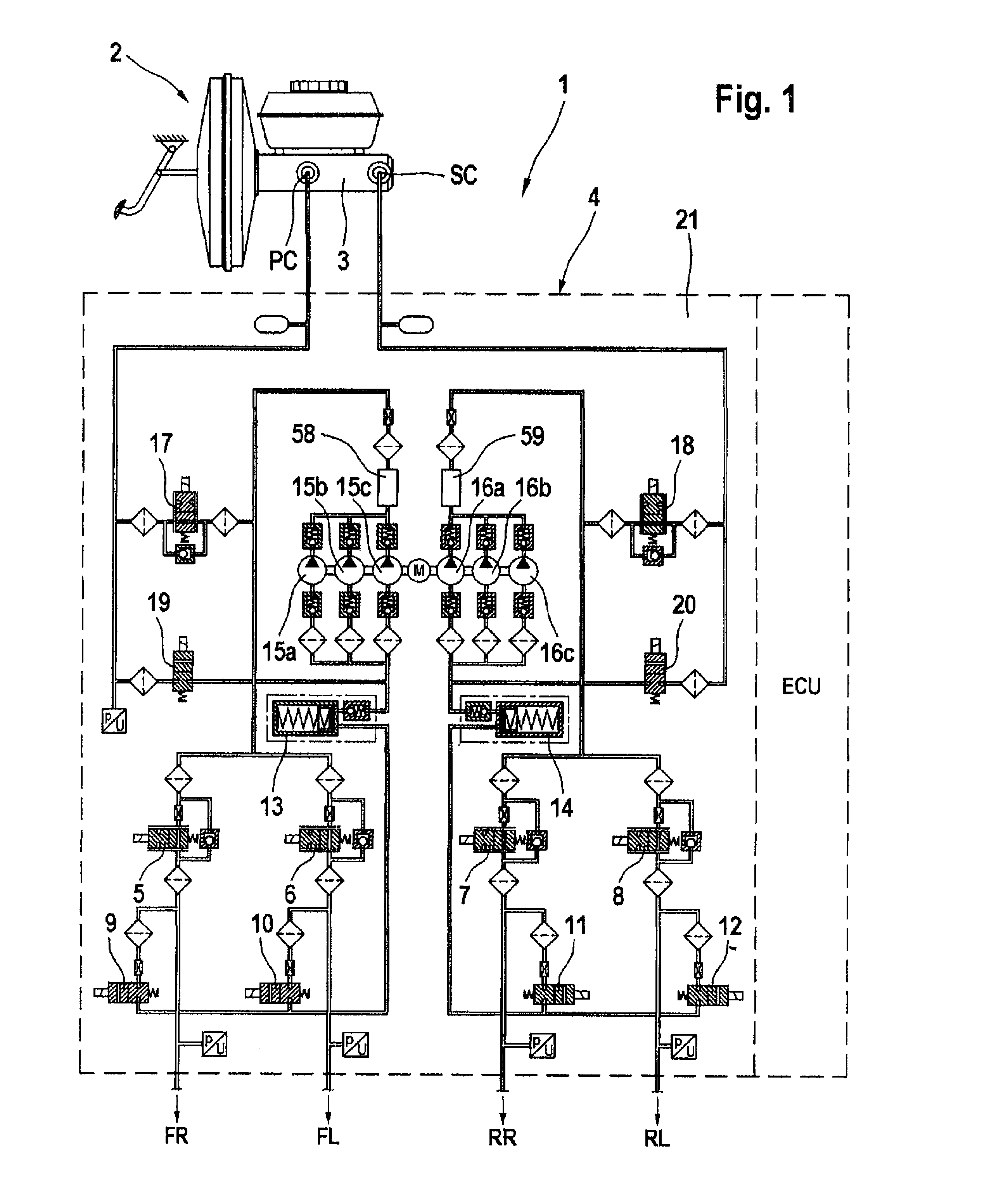
[0024]As shown in FIG. 1, an electrohydraulic braking system 1 comprises an actuating unit 2 with a master cylinder 3 and wheel brakes FR, FL, RR, RL organized in pairs in two different hydraulic circuits, which wheel brakes FR, FL, RR, RL are each connected both in a bundled manner and independently of one another either to a primary pressure chamber PC or to a secondary pressure chamber SC of the master cylinder 3.

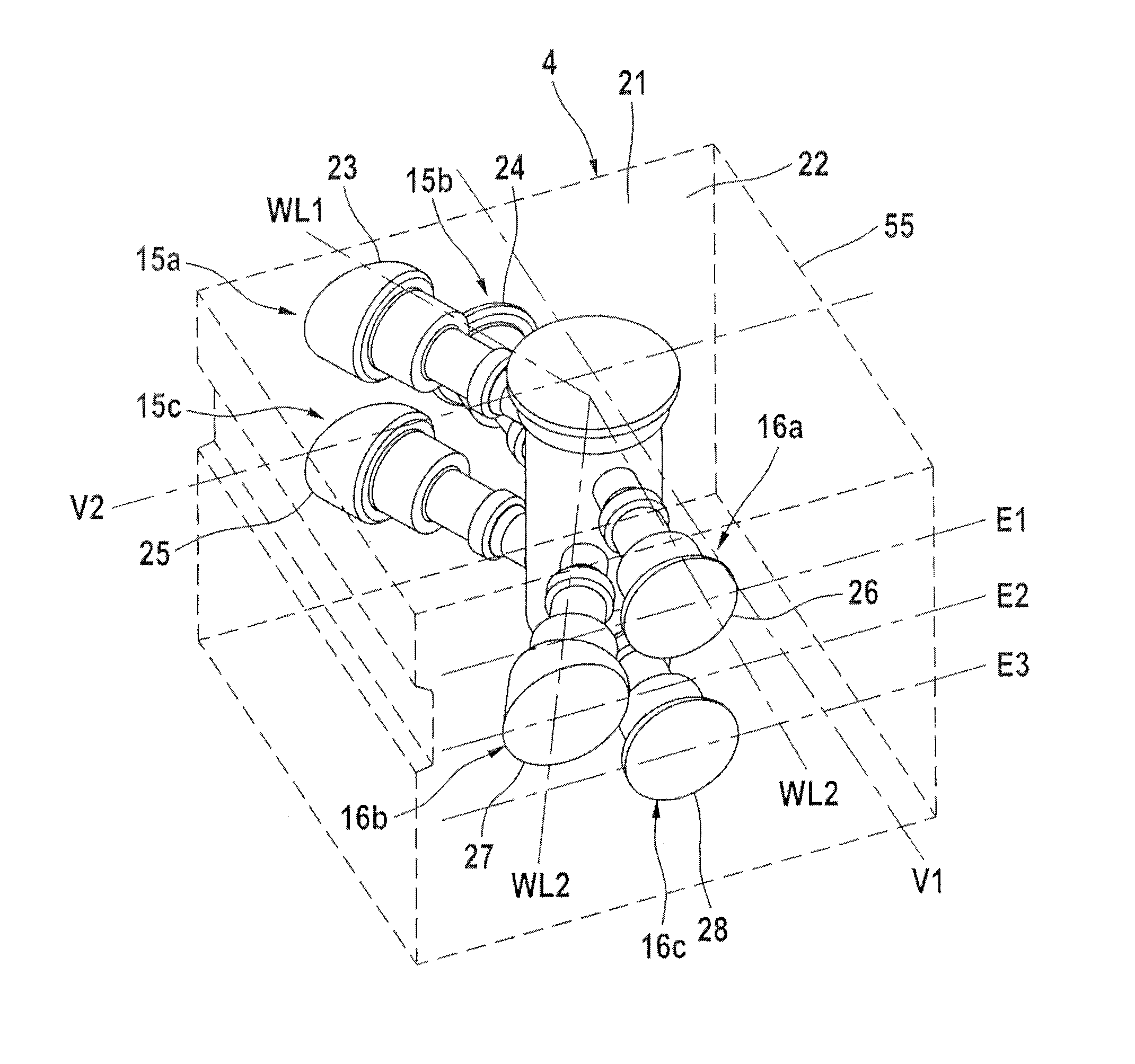
[0025]Also located in the connection between master cylinder 3 and wheel brakes FR, FL, RR, RL is a hydraulic unit 4 with electronic control unit ECU which makes possible slip control for braking or drive. For this purpose the hydraulic unit 4 includes in a receiving body 21 currentlessly open inlet valves 5-8 and currentlessly closed outlet valves 9-12, which valves are connected in pairs upstream of the wheel brakes FR, FL, RR, RL.

[0026]Unnecessarily high pressure build-up within the ABS control cycles is reduced by activating the currentlessly closed outlet valves 9-1...


PUM


Abstract

A hydraulic unit for slip-controlled braking systems has a plurality of receiving holes for transport devices associated with a plurality of hydraulic circuits bundled into groups, wherein the receiving holes are disposed at a distance from each in parallel with the upper side and a drive shaft having eccentrics located at the plane spacing for driving the transport devices. In order to provide a compromise optimized for manufacturing a small, convenient hydraulic unit, it is proposed that three theoretical planes (E1, E2, E3) are arranged in parallel to the upper side, each receiving two V-shaped receiving holes for transport devices disposed at an angle to each other, and that the drive shaft includes three separate eccentrics for driving the transport devices.

Description

CROSS REFERENCE TO RELATED APPLICATIONS[0001]This application is the U.S. National Phase application of PCT International Application No. PCT / EP2008 / 063718, filed Oct. 13, 2008, which claims priority to German Patent Application No. 10 2007 050 101.5, filed Oct. 19, 2007, and German Patent Application No. 10 2008 005 279.5, filed Jan. 19, 2008, the contents of such applications being incorporated by reference herein.FIELD OF THE INVENTION[0002]The invention relates to a hydraulic unit. A unit of this type is suitable preferably for use within an electrohydraulic braking system, a vehicle driver expressing a braking request which is implemented by the braking system, to some extent by-wire, by means of suitable actuators—preferably while taking account of the environmental conditions detected.BACKGROUND OF THE INVENTION[0003]In electrohydraulic braking systems, pressure is built up in wheel brakes either directly with the aid of a pressure source, usually in the form of displacement ...

Claims


Application Information

Patent Timeline
Patent Type & Authority Patents(United States)
IPC IPC(8): B60T13/16B60T8/40
CPCB60T8/4031B60T8/368F04B1/0421F04B53/16F04B1/0538F04B53/162
Inventor GASTAUER, HEIKOFISCHBACH-BORAZIO, PETRAHINZ, AXELGREIFF, UWE
Owner CONTINENTAL TEVES AG & CO OHG
Why Eureka
Try Eureka