
Ink-jet recording apparatus

a technology of recording apparatus and inkjet, which is applied in the direction of printing, etc., can solve the problems of deterioration of recording quality, inconvenient operation, and difficulty in production, and achieve the effect of high quality

Active Publication Date: 2013-08-06
BROTHER KOGYO KK
View PDF30 Cites 3 Cited by
  • Summary
  • Abstract
  • Description
  • Claims
  • Application Information

AI Technical Summary

Benefits of technology

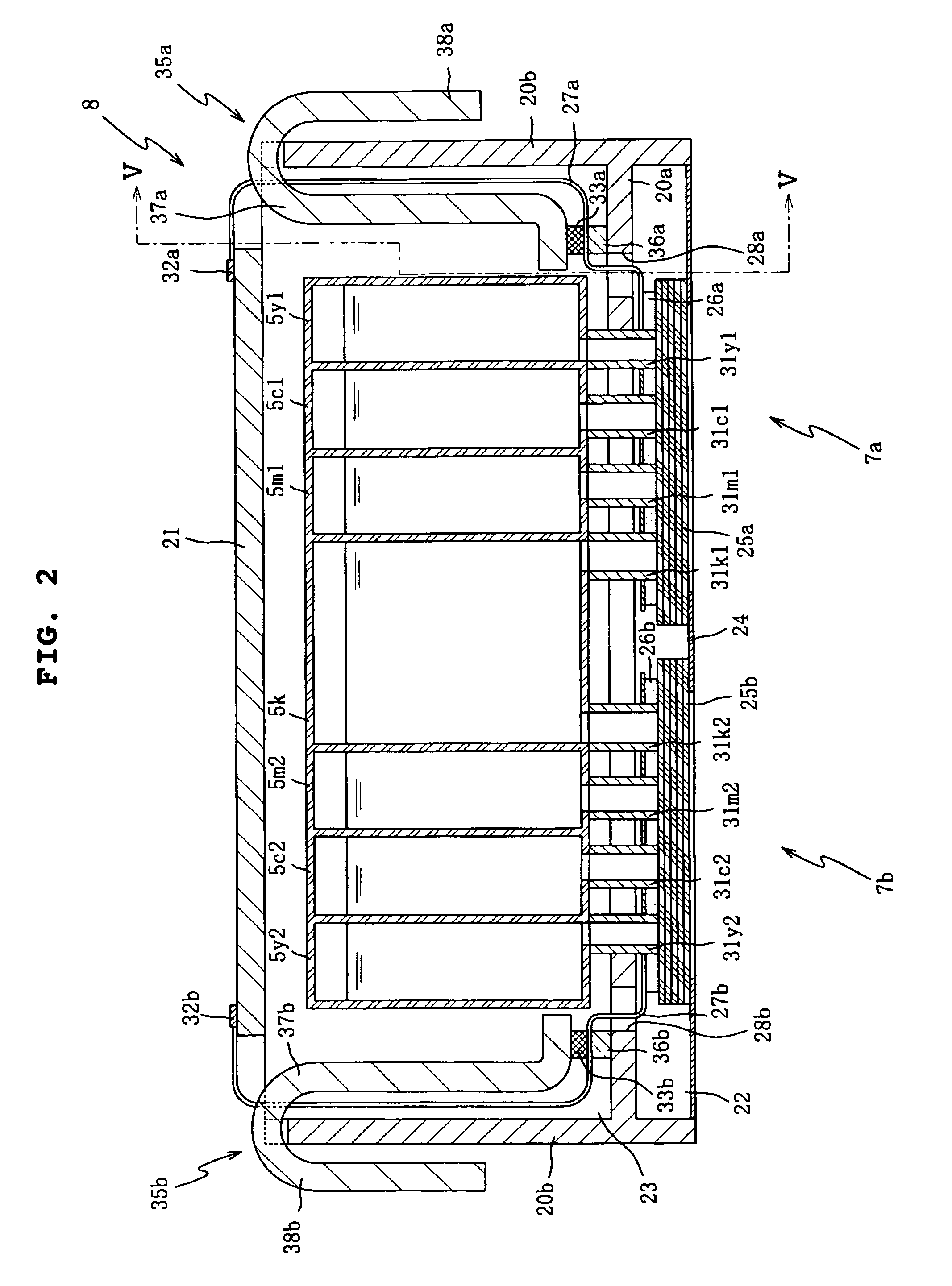
[0016]According to the ink-jet recording apparatus of the present invention, the recording head has the plurality of nozzles arranged in array in the first direction for each of the ink colors. The flexible wiring member extends from the recording head in the second direction perpendicular to the first direction. The driving circuit, which outputs the driving signal to discharge the ink from the nozzles, is arranged on the wiring member. Therefore, the wiring from the driving circuit to the recording head, which is formed in the wiring member, can be formed within a width corresponding to the length of the nozzle array. Therefore, the wiring density can be lowered as compared with a case in which the wiring member extends in the first direction. The wiring can be formed with ease, and it is possible to reduce the production cost.
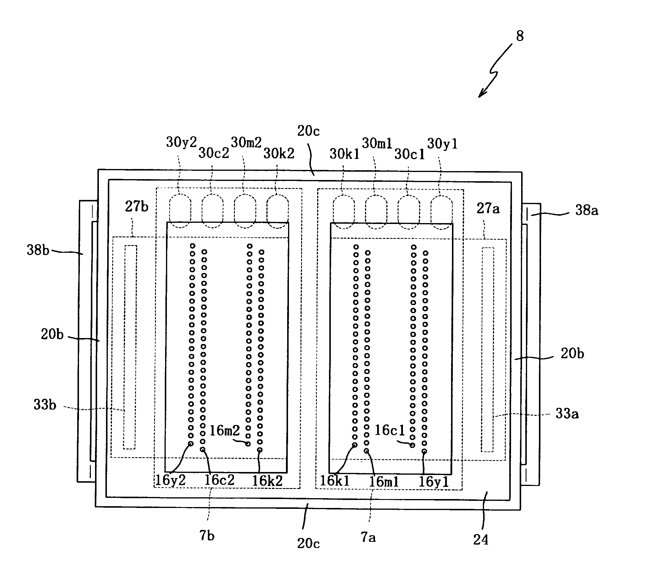
[0018]In the ink-jet recording apparatus, the ink of the dark color may be an ink of the darkest color, and the ink of the light color may be an ink of the lightest color. In this case, the nozzle arrays of the recording head may be arranged for the plurality of ink colors such that the nozzle array, which corresponds to the lightest ink color, may be disposed at a position nearest to the driving circuit, for the following reason. That is, in the case of the ink of the light color, the recording disturbance is hardly conspicuous, even when the discharge characteristic from the nozzles is changed by being affected by the heat from the driving circuit. Therefore, it is possible to perform the high quality recording.
[0019]In the ink-jet recording apparatus, as the color of the ink becomes darker, the nozzle array which jets the ink of darker colors may be arranged farther from the driving circuit. Therefore, even when the driving circuit generates the heat, then the darker ink color is affected by the heat to a smaller extent, and it is possible to decrease the recording disturbance. The disturbance is more inconspicuous in the case of the lighter ink color, even when the recording is disturbed by the influence of the heat. Therefore, it is possible to perform the high quality recording.
[0020]The inks of the plurality of colors may include at least two inks of colors which are substantially equivalent in lightness and darkness, and a nozzle array of the nozzle arrays, which jets an ink of a color which is more frequently discharged, of the at least two inks, may be arranged far from the driving circuit. When the arrangement is made as described above, it is possible to decrease the influence brought about by the heat generation of the portion of the recording head corresponding to the nozzle array having the high discharge frequency and by the thermal conduction from the driving circuit to the recording head. Thus, it is possible to perform the high quality recording.
[0022]The recording head may include two head bodies which have the plurality of nozzle arrays respectively and which are arranged in the second direction; the flexible wiring member may include two wiring sections which are connected to the two head bodies and which extend in the second direction oppositely to each other; and the driving circuit may include circuits which are provided for the two wiring sections respectively. In this arrangement, the nozzle arrays for jetting the ink of the dark color may be arranged on sides nearer to mutually adjoining side edges of the two head bodies. As described above, when the nozzle arrays, which jet the dark color ink, are arranged as described above when the two head bodies are provided, then the nozzle arrays, which correspond to the dark ink color, are disposed at the positions farthest from the driving circuit, and it is possible to decrease the influence of the heat from the driving circuit.
[0023]The ink-jet recording apparatus may further comprises a heat sink which is arranged in contact with the driving circuit. The heat sink makes it possible to release the heat generated by the driving circuit to the outside. It is possible to reduce the thermal conduction to the recording head.

Problems solved by technology

In the case of the pale or light color such as the yellow ink, the disturbance is inconspicuous even when the landing position and / or the dot size is disturbed on the recording medium.
Therefore, the disturbance appears as the deterioration of the recording quality.
The production becomes difficult, and the production cost becomes expensive.
The discharge characteristics of the inks are changed at the both ends of the nozzle arrays, and the recording quality on the recording medium is deteriorated.
However, a problem has arisen such that the recording is disturbed, and the recording quality is deteriorated.

Method used


Image

  • Ink-jet recording apparatus
  • Ink-jet recording apparatus
  • Ink-jet recording apparatus

Examples


first embodiment

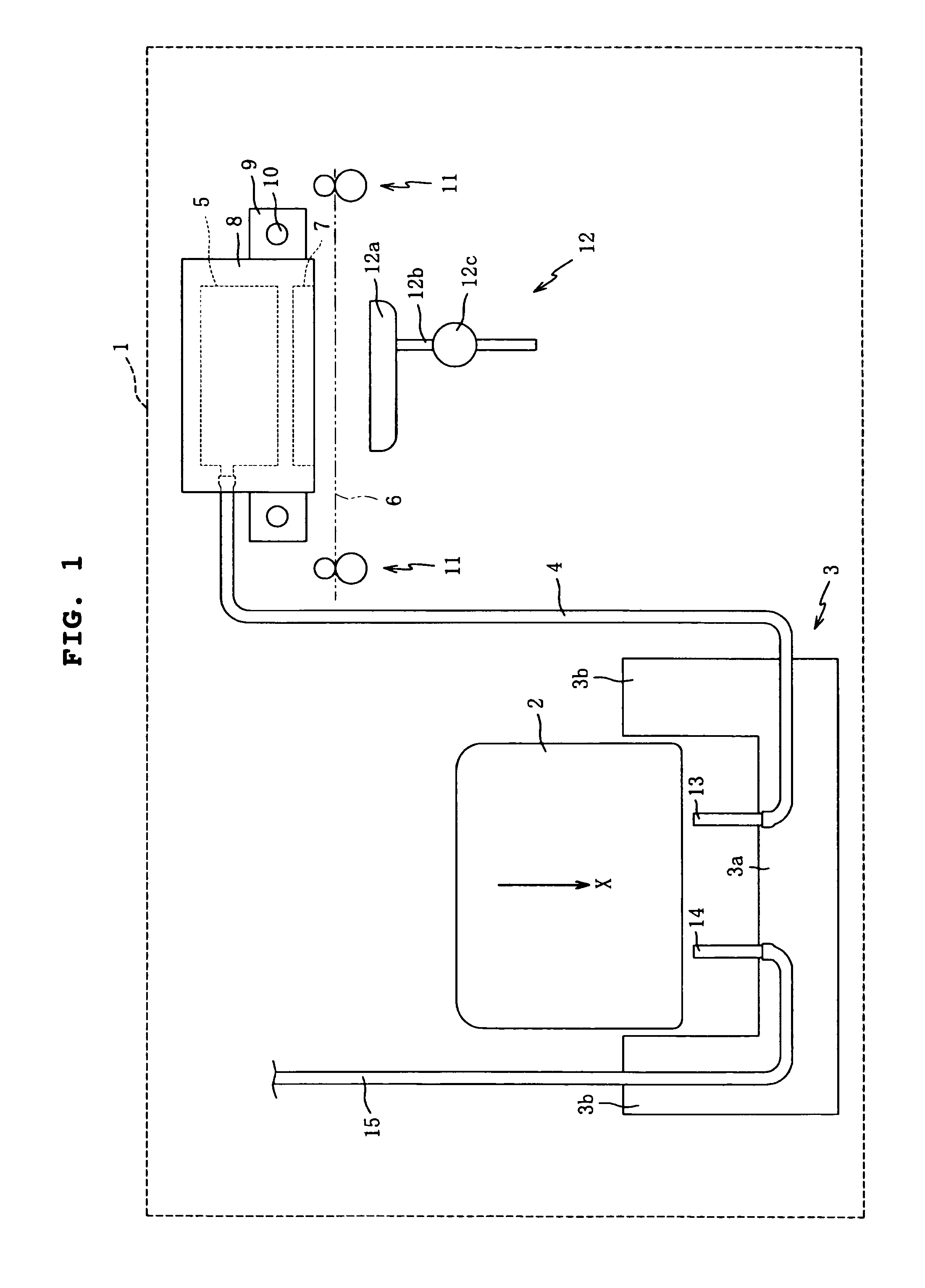
[0037]The ink-jet recording apparatus 1 includes a mounting unit 3 to which an ink cartridge 2 is detachably mounted, an ink tank 5 which stores the ink supplied from the ink cartridge 2 through an ink supply tube 4, a recording head 7 which discharges the ink stored in the ink tank 5 toward a recording medium 6, a carriage 9 which carries a recording head unit 8 provided with the ink tank 5 and the recording head 7 and which makes the reciprocating motion in the linear direction, a carriage shaft 10 which guides the reciprocating motion of the carriage 9, a transport mechanism 11 which transports the recording medium 6, and a purge unit 12. It is assumed that white printing paper is used as the recording medium 6 in the

[0038]The ink cartridge 2 is provided for each of color inks of a plurality of colors including, for example, cyan, magenta, yellow, and black. The ink cartridge 2 is mounted to the ink-jet recording apparatus 1 to make it possible to perform the color printing.

[0039...

third embodiment

[0063]The recording head 207 of the third embodiment has four arrays of nozzles. A flexible wiring board (wiring member) 227 extends in the extending direction of the arrays. An IC chip 233 is carried on the flexible wiring board 227. In this embodiment, the nozzles are divided into those belonging to four groups A, B, C, D arranged in the nozzle array direction. In the direction perpendicular to the arrays, four arrays of the nozzles belong to the every identical group. Specifically, those arranged in the direction directed proximally from the position farthest from the IC chip 233 are the nozzles 216k for the black ink as the nozzle group A, the nozzles 216m for the magenta ink as the nozzle group B, the nozzles 216c for the cyan ink as the nozzle group C, and the nozzles 216y for the yellow ink as the nozzle group D. That is, the IC chip 233 is arranged at the position which is separated farther from the nozzle group A corresponding to the dark ink color than from the nozzle grou...


PUM


Abstract

An ink-jet recording apparatus includes a recording head which jets inks, and a cable which is connected to the recording head and which is provided with a driving circuit for applying a driving voltage of the recording head. The recording head is formed with nozzle arrays for jetting an ink of a dark color and an ink of a light color respectively. The nozzle array, which jets the ink of the dark color, is disposed farther from the driving circuit than the nozzle array which jets the ink of the light color. The nozzle array, which jets the ink of the dark color, is hardly affected by the heat from the driving circuit. Therefore, the deterioration of the recording quality, which would be otherwise caused by the disturbance of ink discharge from nozzles, is suppressed.

Description

BACKGROUND OF THE INVENTION[0001]1. Field of the Invention[0002]The present invention relates to an ink-jet recording apparatus. In particular, the present invention relates to an ink-jet recording apparatus in which nozzles for discharging inks of a plurality of colors are arranged or aligned so that the influence of heat exerted by a driving circuit is inconspicuous.[0003]2. Description of the Related Art[0004]As disclosed in Japanese Patent Application Laid- open Nos. 2002-240306 (FIGS. 4 and 6) corresponding to U.S. Pat. Nos. 6,679,595 and 2003-80793 (FIGS. 6, 9, and 14) corresponding to U.S. Patent Application Publication No. 2003 / 0063449 A1, an ink-jet recording apparatus is known, in which inks are discharged from a recording head to perform the recording on a recording medium. The recording head includes a plurality of nozzles which are arranged in arrays, a cavity plate which has a plurality of pressure chambers and which is formed to have a substantially rectangular stacke...

Claims


Application Information

Patent Timeline
Patent Type & Authority Patents(United States)
IPC IPC(8): B41J2/05B41J2/175B41J2/01
CPCB41J2/17526
Inventor KUBO, TOMOYUKI
Owner BROTHER KOGYO KK
Learn More