Method and system for scanning in WLAN

a radio communication system and scanning technology, applied in the field of radio communication systems, can solve the problems of not being able to accept real-time application services, scanning latency still needs to be solved, detection latency and association/authentication latency have been reduced to an acceptable degree, etc., to improve network security, reduce the time delay of the whole scanning process, avoid the effect of losing the probe response messag

Inactive Publication Date: 2013-08-06
SIEMENS AG
View PDF24 Cites 0 Cited by
  • Summary
  • Abstract
  • Description
  • Claims
  • Application Information

AI Technical Summary

Benefits of technology

[0012]SUMMARY In view of what described above, the solution by the embodiments discussed herein to the technical problem is to provide a method and a system for scanning in a radio communication system, in particular for a WLAN, and compared to the prior art, by using the method and system of the embodiments not only the time delay of scanning is further reduced, but also the network security is improved and the difficulty in its realization is reduced.

Problems solved by technology

Currently, the detection latency and the association / authentication latency have been reduced to an accepted degree, while the scanning latency still is a problem to be solved.
This is not acceptable to a real-time application service.
The problem of the scanning latency originates from the IEEE 802.11 specifications which suggests that when switching an AP, an MS should transmit a probe message on all channels one by one, and stop communicating with the original AP to wait for a probe response message.
It can be seen that, according to the proposals in the IEEE 802.11 specifications, the scanning latency for an MS during its switching will be very big, which will affect the normal operation of the MS and the system.
However, there are problems in the FMLS method, first, the AP probed needs to wait according to the response latency information after the fast scan probe message has been received, and the probe response message can be transmitted only within the time required by the response latency.
The response latency is set to avoid losing the probe response message, but it also increases the scanning latency.
Secondly, the another AP probed transmits the probe response message to the MS via the IP route, which will not only greatly reduce the network security, but also is hard to realize.

Method used


Image

  • Method and system for scanning in WLAN
  • Method and system for scanning in WLAN
  • Method and system for scanning in WLAN

Examples


Embodiment Construction

[0034]Reference will now be made in detail to the preferred embodiments, examples of which are illustrated in the accompanying drawings, wherein like reference numerals refer to like elements throughout.

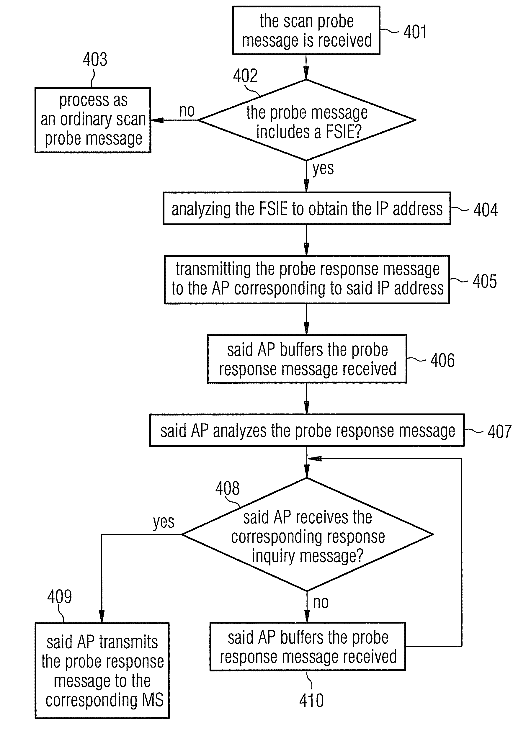
[0035]A core concept of the embodiments is that: the MS transmits on all channels a probe message containing the IP address of the original AP of the MS and the MAC address of the MS, switches to the original channel, transmits the response inquiry message to the original AP, and receives the probe response message within a predetermined period; if the AP receiving the probe message on the channel is not the original AP, then that AP transmits the probe response message containing the MAC address to the original AP according to the IP address; the original AP buffers the probe response message received by it, and transmits the probe response message to the MS according to the MAC address after the response inquiry message sent by the MS has been received. Therefore, the time delay of...


PUM


Abstract

The embodiments disclose a method for scanning in a radio communication system, in particular in a WLAN (Wireless Local Area Network), including transmitting by a MS on all channels a probe message containing the IP address of the original AP of the MS and an MAC address of the MS; switching to the original channel; transmitting a response inquiry message to the original AP; and receiving a probe response message within a predetermined period, wherein, if the AP of the probe message received on the channel is not the original AP, then the AP transmits the probe response message containing the MAC address to the original AP according to the IP address; and the original AP buffers the probe response message received, and transmits the probe response message to the MS according to the MAC address after the response inquiry message sent by the MS has been received. The embodiments further disclose a scanning system in a WLAN. By using the method and system, not only the time delay during the scanning is reduced, but also the network security is improved and the difficulty for realization is decreased.

Description

CROSS REFERENCE TO RELATED APPLICATIONS[0001]This application is based on and hereby claims priority to International Application No. PCT / EP2007 / 059903, filed on Sep. 19, 2007, and Chinese Application No. 200610113229.1, filed Sep. 20, 2006, the contents of both of which are hereby incorporated by reference.BACKGROUND[0002]1. Field[0003]The embodiments discussed herein relate to the technical field of a radio communication system, in particular in the technical field of WLAN (Wireless Local Area Network), and specifically to a method and a system for scanning in a radio communication system.[0004]2. Description of the Related Art[0005]While a mobile station (MS) roams in a WLAN, when the quality of the communication between the MS and an access point (AP) deteriorates to a certain degree, the MS will switch from the original AP to a new AP. During the process for the MS to switch the AP, if the MS is performing a real-time application service, it is desirable that the influence made...

Claims


Application Information

Patent Timeline
Patent Type & Authority Patents(United States)
IPC IPC(8): H04W4/00H04W8/26H04W24/00H04W36/06H04W48/08H04W84/12H04W88/08
CPCH04W24/00H04W8/26H04W36/06H04W48/08H04W84/12H04W88/08
Inventor CHEN, LING
Owner SIEMENS AG
Why Eureka
Try Eureka