Snap ring attachment and snap ring attaching tool

a technology of snap ring and attachment groove, which is applied in the direction of metal-working hand tools, metal-working apparatuses, metal-working apparatuses, etc., can solve the problems of not being able to attach the snap ring to the other attachment groove after insertion of the piston pin, and complicated configuration, so as to simplify the attachment step, improve the durability of the components of the attachment, and simplify the construction

Active Publication Date: 2013-08-13
HIRATA & CO LTD
View PDF7 Cites 6 Cited by
  • Summary
  • Abstract
  • Description
  • Claims
  • Application Information

AI Technical Summary

Benefits of technology

[0031]According to the snap ring attachment and tool having the above-described configuration, durability of the components constituting the attachment can be improved while achieving simplification of the construction, miniaturization, automatization of the attachment operation, simplification of the attachment step, and others, whereby the snap ring can be stably and assuredly attached to the attachment groove.

Problems solved by technology

However, in this attachment, an operator manually performs all of an operation of supplying the snap ring into the guide cylinder, a pushing operation, a radially contracting operation, and an attaching operation based on rotation, and the attaching operation is not automatically carried out.
On the other hand, when driving this pushing member by, e.g., an actuator to achieve automation in this attachment, a reciprocation driving actuator configured to push in the pushing member and a rotation driving actuator configured to rotate the pushing member are required, thereby resulting in a complicated configuration.
However, in this attachment, since the snap ring is attached to one of the attachment grooves alone in a state that the piston pin is not inserted in the pin hole of the piston, the snap ring cannot be attached to the other attachment groove after insertion of the piston pin.

Method used


Image

  • Snap ring attachment and snap ring attaching tool
  • Snap ring attachment and snap ring attaching tool
  • Snap ring attachment and snap ring attaching tool

Examples


Embodiment Construction

[0110]An embodiment according to the present invention will now be described hereinafter with reference to the accompanying drawings.

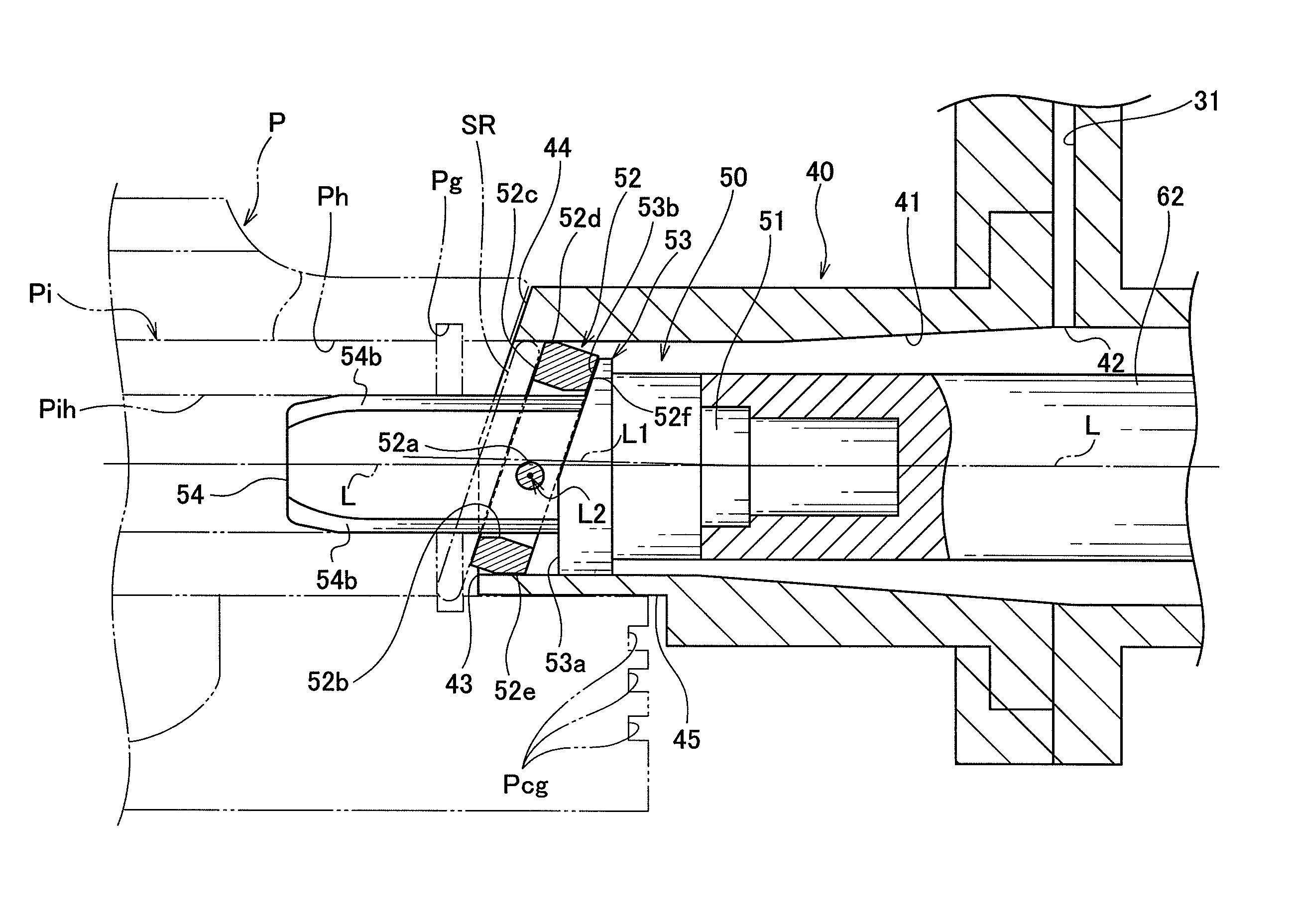
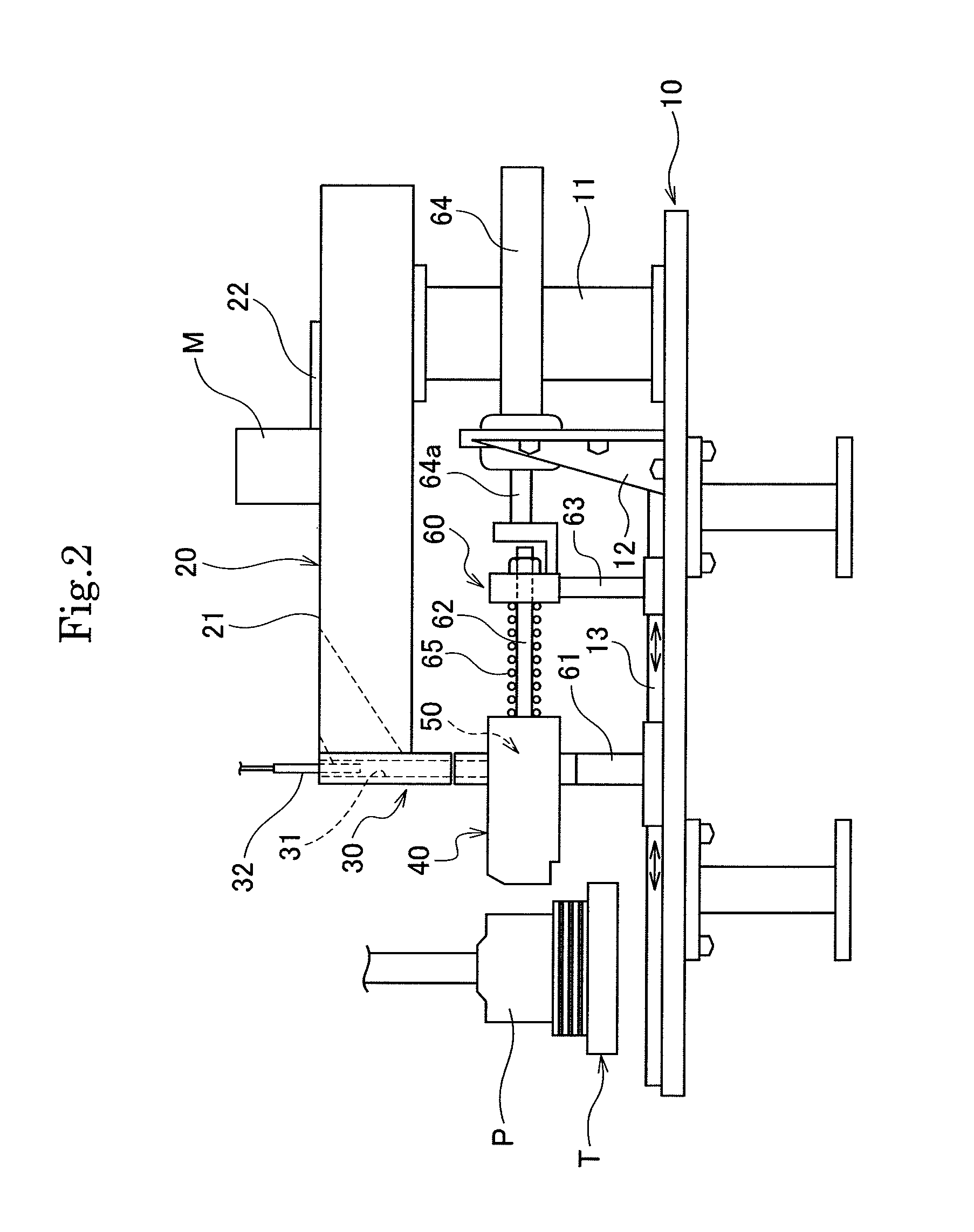
[0111]As shown in FIG. 2, this snap ring attachment includes a base 10, a supply mechanism 20 that is provided on the base 10 and supplies a snap ring SR, a radial contraction mechanism 30 that radially contracts the snap ring SR, a guide cylinder 40 that is separably engaged with a piston P as a workpiece and guides the snap ring SR toward an attachment groove Pg of the piston P, a posture changing and pressing mechanism 50 that presses the snap ring SR to change a posture of the snap ring and presses the snap ring into the attachment groove Pg, a driving mechanism 60 that is provided on the base 10 and exercises driving force to generate pressing force in the posture changing and pressing mechanism 50.

[0112]It is to be noted that, in an upper region of the base 10, the piston P as the workpiece is held by a holder table T to be sequentially carried i...


PUM

PropertyMeasurementUnit
angleaaaaaaaaaa
pressing forceaaaaaaaaaa
Phaaaaaaaaaa

Abstract

A snap ring attachment includes a guide cylinder (40) defining a guide path (41) having a region of a supply port side of a snap ring exhibiting a circular section and a region of an exit side of the snap ring exhibiting an oval section and continuously varying from the circular section to the oval section, so as to guide the snap ring toward an attachment groove, a posture changing and pressing mechanism (50) provided in the guide cylinder for pressing the snap ring supplied in an upright state vertical to the extending direction of the guide path while being radially contracted, to tiltingly move it, then again erect it, and press it while changing its posture to be pushed into the attachment groove, and a driving mechanism (60) for exerting driving force to generate pressing force in the posture changing and pressing mechanism.

Description

TECHNICAL FIELD[0001]The present invention relates to a snap ring attachment and a snap ring attaching tool that automatically attach a C-type snap ring having a gap to an attachment groove of a workpiece, and more particularly to a snap ring attachment and a snap ring attaching tool that attach a snap ring to an annular attachment groove formed at each of both ends of a pin hole into which a piston pin for coupling a connecting rod with a piston of an internal-combustion engine is inserted to prevent the piston pin from coming off.BACKGROUND ART[0002]As a conventional snap ring attachment, as shown in FIG. 1A to FIG. 1C, there is known a snap ring attachment including a guide cylinder 1 that defines a guide path 1a having a circular cross section to guide a snap ring SR while directly coming into contact with a piston P, a pushing member 2 having a discoid pressing portion 2a to push the snap ring SR contracted in a diametric direction and introduced in the guide cylinder 1 toward ...

Claims


Application Information

Patent Timeline
Patent Type & Authority Patents(United States)
IPC IPC(8): B23P19/04B23P11/00
CPCB23P19/084B25B27/20Y10T29/53843Y10T29/53783Y10T29/53739Y10T29/53613Y10T29/53678Y10T29/5363
Inventor UEDA, MICHITOMOTAKAMURA, KOTAROKAWAMOTO, YUKIHIRO
Owner HIRATA & CO LTD
Why Eureka
Try Eureka