Wound closure and drainage system

a drainage system and wound technology, applied in the direction of machines/engines, liquid fuel engines, positive displacement liquid engines, etc., can solve the problems of unreliability, complex and expensive methods of isolating the pump, and bulky and inconvenient burden for patients, etc., to achieve convenient use

Active Publication Date: 2013-08-13
M E A C ENG LTD
View PDF81 Cites 42 Cited by
  • Summary
  • Abstract
  • Description
  • Claims
  • Application Information

AI Technical Summary

Benefits of technology

[0012]It is the purpose of this invention to alleviate all the above listed deficiencies, by providing a wound drainage enclosure and vacuum system, which are impervious to contamination and easy to use.
[0015]The bleeding hole renders the wound closure vented or non-airtight, as distinguishable from conventional wound closures. The flow of air from the bleeding hole in the wound closure, in response to the negative pressure created by the vacuum pump, facilitates the removal of exudate, which might otherwise coagulate, dry-up and occlude the tubing.
[0036]Thus, indirect means are provided for controlling or monitoring the level of negative pressure applied to the wound, without making any direct connection to a vacuum sensor, transducer or gage to any portion of the system, which has the negative pressure applied to it. The indirect negative pressure monitoring and control result from the need to dispose of any portion of the system, which may come in contact with the pumped media, which is likely to be contaminated or infectious. Accordingly, all the disposable components in the system may be relatively low in cost, to promote discarding them after use. Pressure transducers, vacuum gages or sensors, are relatively costly, and thus not considered disposable.

Problems solved by technology

Current negative pressure wound drainage systems such as the ones described above suffer from the following deficiencies:Since the negative pressure applied to the wound area is created by pump suction, the flow into the pump is likely to contaminate the pump, or conversely, to require costly and complex methods of isolating the pump from the wound exudate such as antibacterial filters.The wound exudate is collected in a rigid canister, which must be large enough to prevent it from overflowing, and thus it is bulky and an inconvenient burden for ambulatory patients, who carry a portable system with them.Conventional wound drainage systems utilize an air tight seal of the wound, which is helpful in obtaining and maintaining negative pressure, but requires a pressure relief or bleed valve to produce the pressure cycling desirable to obtain accelerated wound closure, as described in WO 96 / 05873.A sealed wound dressing or enclosure, when under negative pressure, will promote migration of the exudate toward the negative pressure source, through the connecting tube, which may occlude, should the exudate coagulate.The need to monitor and control the negative pressure level in conventional systems requires the use of a vacuum transducer, gage or relief valve, which must be connected to the suction tube, which is subject to contamination.
Cleaning, disinfecting or isolating the negative pressure monitoring or controlling device are complex, costly and un-reliable.

Method used


Image

  • Wound closure and drainage system
  • Wound closure and drainage system
  • Wound closure and drainage system

Examples


Embodiment Construction

[0040]The present invention provides a system and a method of treating and healing of a body wound, by applying a negative pressure to the wound, over an area sufficient to promote migration of epithelial and subcutaneous tissue toward the wound.

[0041]It is appreciated that the detailed description that follows is intended only to illustrate certain preferred embodiments of the present invention. It is in no way intended to limit the scope of the invention, as set out in the claims.

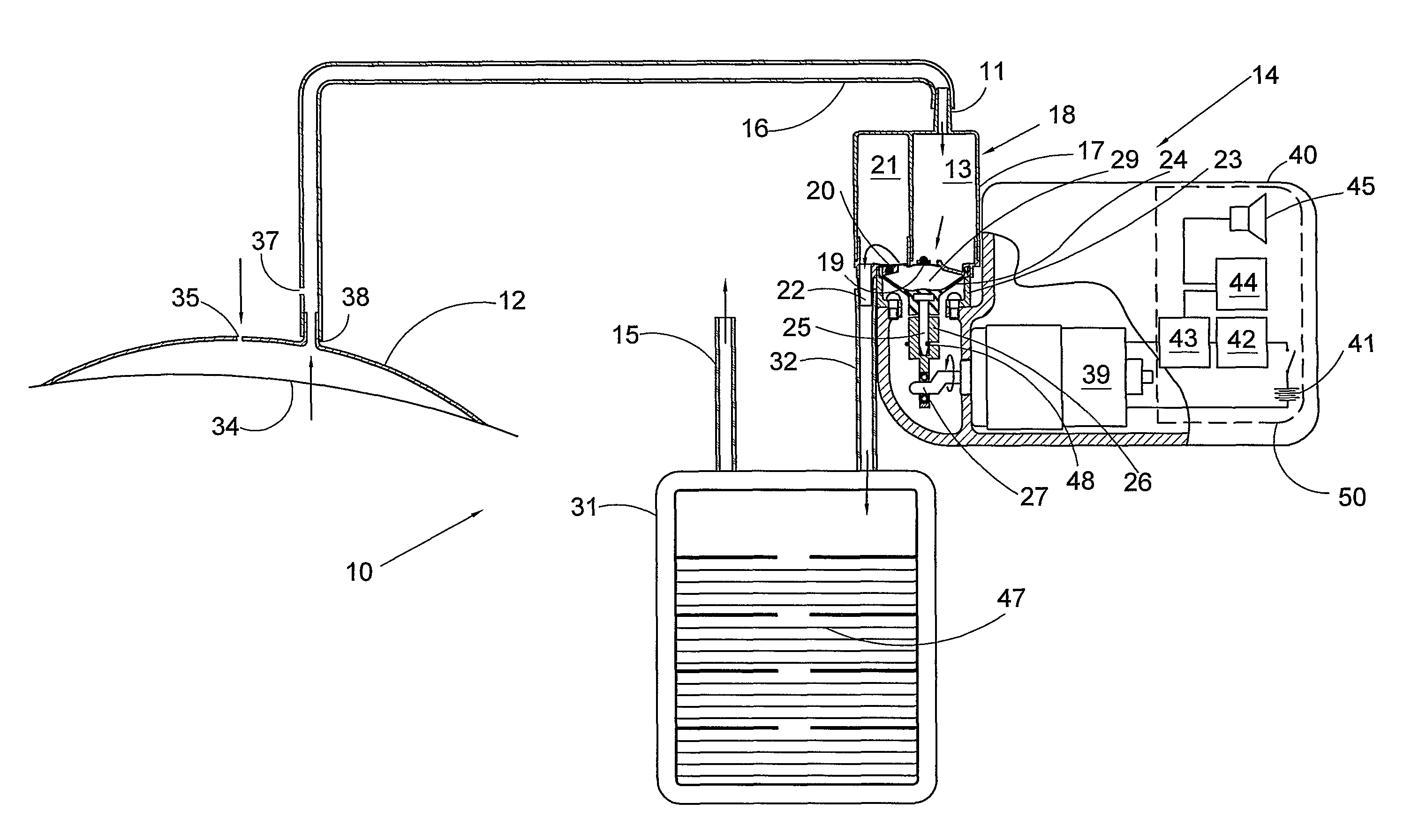
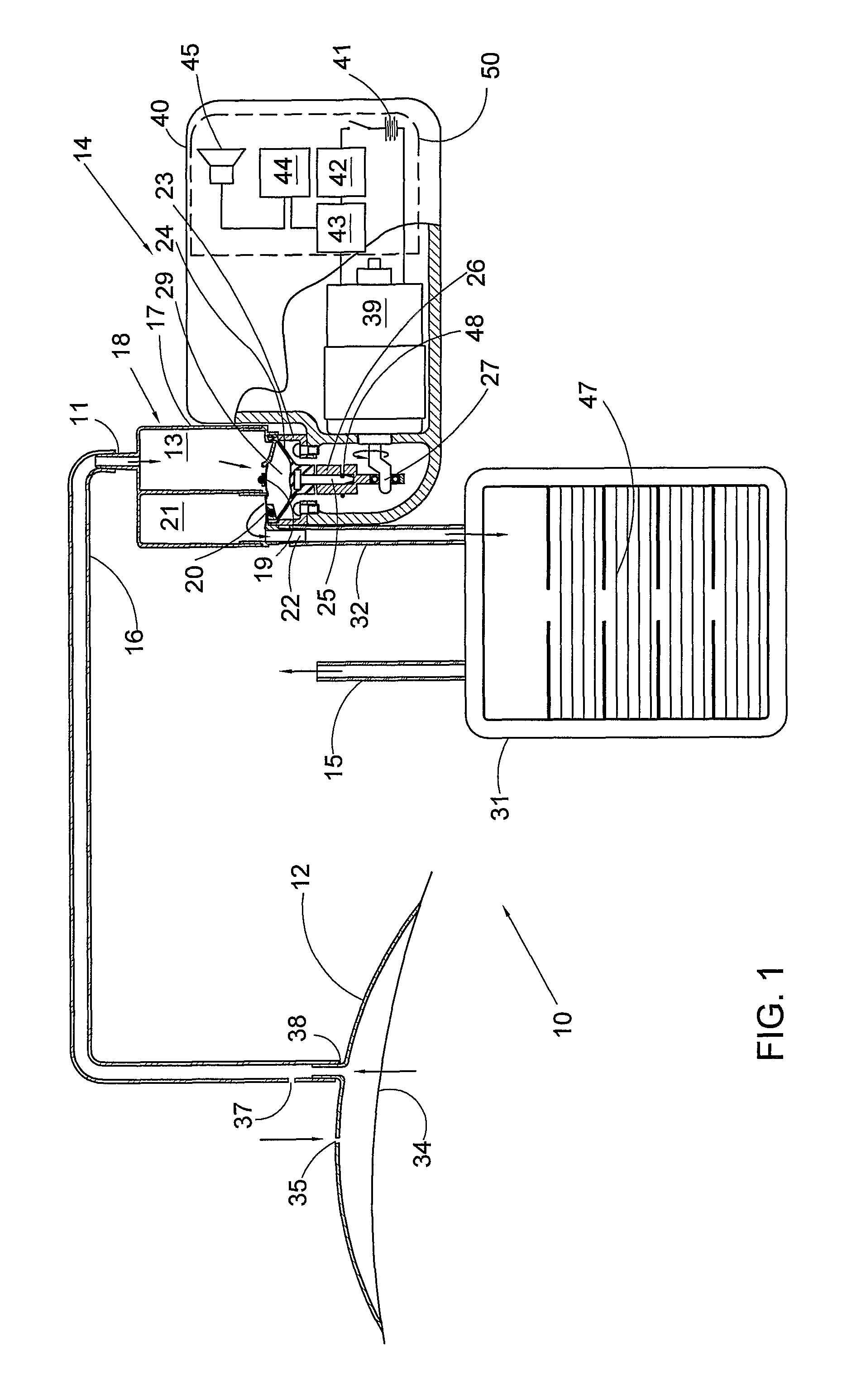
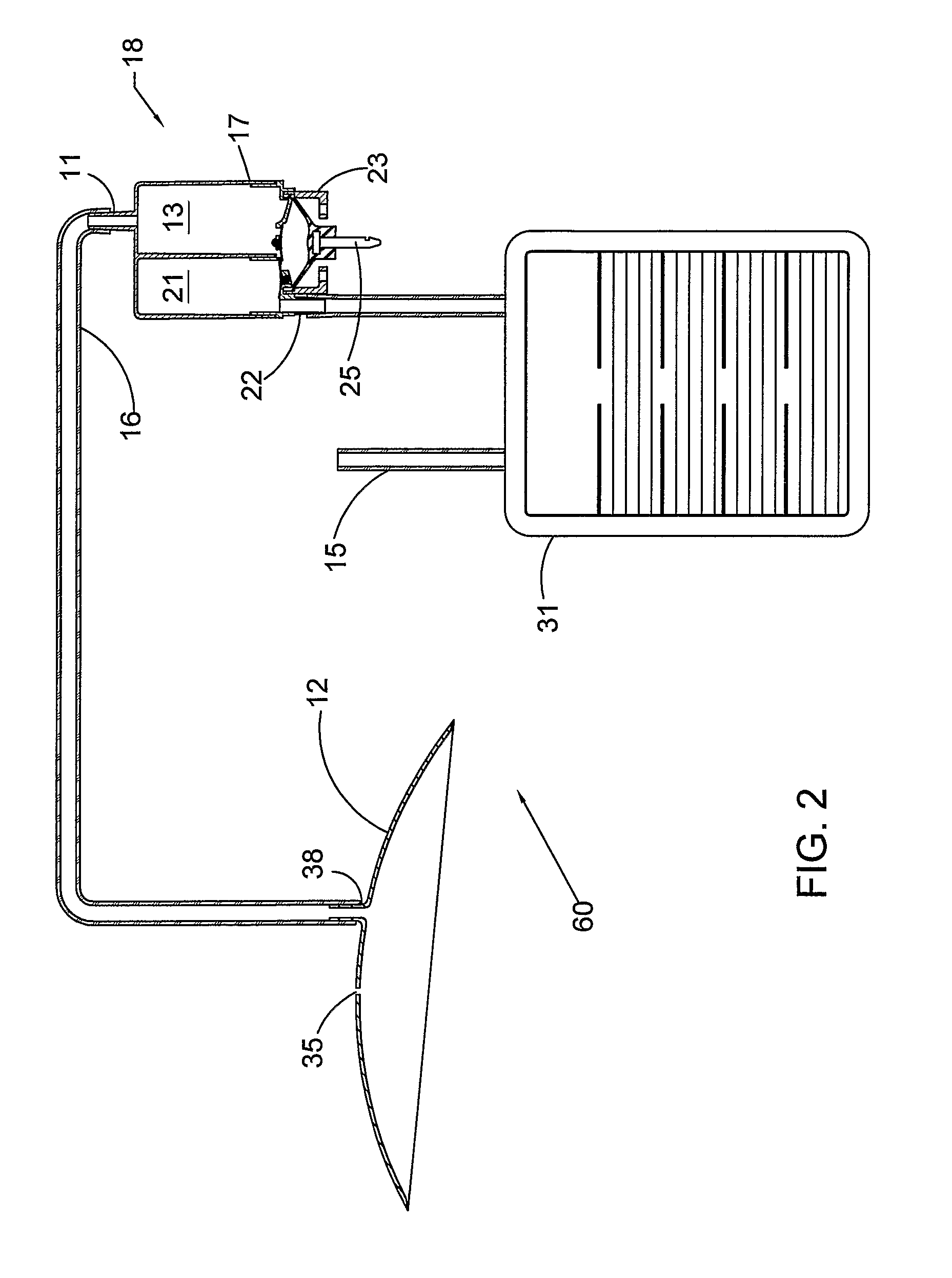
[0042]With reference to FIG. 1, in accordance with the present invention, a vacuum system 10 for draining an open wound from liquids exuded therefrom comprises a wound enclosure 12, a vacuum pump 14, and waste collection bag 31. The wound enclosure 12 is connected by a suction tube 16 to an inlet 11 of the vacuum pump. The waste collection bag 31 is connected to an outlet 22 of the vacuum pump. Thereby, when the vacuum pump 14 is operated, the drained liquids flow through the pump into the waste bag 31.

[0...


PUM


Abstract

The invention relates to a tilt and slide cover in a vehicle roof. The tilt and slide cover comprises a cover and a frame, which is supported in lateral guides of a roof opening. The special feature of the tilt and slide cover lies in the fact that the cover is arranged relatively moveable in relation to the frame and can be locked to and released from this. The frame comprises a plastic section, into which the slide guide and other fittings such as slide cheek holders or the like can be integrated in one piece. It is also possible to fix the rear water collection channel directly on the frame.

Description

FIELD OF TH INVENTION[0001]This invention relates generally to wound healing, and more specifically to healing of wounds by negative pressure drainage.BACKGROUND OF THE INVENTION[0002]Negative pressure applied to a wound enhances drainage of fluids or exudate from the wound and promotes tissue growth and wound healing. This method of healing (known as “cupping”) was exercised since the times of ancient Greek physicians until the 19th century.[0003]WO 96 / 05873 describes a therapeutic apparatus for stimulating healing of wounds. The apparatus comprises a porous foamed pad which is sealed on the wound and connected by a tube to an inlet of a canister. A vacuum pump is connected to an outlet of the canister. A bacterial filter positioned over the outlet of the canister protects the vacuum pump from contamination by wound drainage fluids sucked into the canister. The pump, the canister and control circuitry are disposed in a case.[0004]WO 97 / 18007 discloses a portable wound treatment app...

Claims


Application Information

Patent Timeline
Patent Type & Authority Patents(United States)
IPC IPC(8): A61M1/00
CPCA61M1/0031A61M1/0066A61M1/0088A61M1/0092F04B53/22A61M1/0023A61M1/0027A61M1/0072F04B45/047A61M1/0037A61M2205/121F04B43/04A61M1/732A61M1/75A61M1/74A61M1/82A61M1/80A61M1/964A61M1/96A61M1/73A61M1/962A61M1/60A61M1/72A61M2205/3344
Inventor ADAHAN
Owner M E A C ENG LTD
Why Eureka
Try Eureka