
Vehicle capable of indicating a position of an electric power-receiving unit

a technology of electric power-receiving unit and vehicle, which is applied in the field of vehicles, can solve the problems of user burden, difficulty in visually perceiving, and difficulty in and achieve the effect of easy finding the position of the charging connector

Active Publication Date: 2013-08-13
TOYOTA JIDOSHA KK
View PDF14 Cites 10 Cited by
  • Summary
  • Abstract
  • Description
  • Claims
  • Application Information

AI Technical Summary

Benefits of technology

[0009]The present invention has been made to solve such problems, and an object of the present invention is to provide a vehicle that enables a user to easily find out the position of a charging connector regardless of the circumstances of vehicle surroundings.
[0018]According to the present invention, it is possible to implement a vehicle that enables a user to easily find out the position of a charging connector regardless of the circumstances of vehicle surroundings.

Problems solved by technology

In the case that the electric-powered vehicle is externally charged in a garage of each household, a lighting fixture is not always fully equipped, in contrast to the case that fuel is resupplied at the fueling station.
Accordingly, as disclosed in Japanese Patent Laying-Open No. 06-325834, even if a lamp is provided in a housing provided at the vehicle, there arises a problem of difficulties for a vehicle user in visually perceiving the position of the charging port in the case that vehicle surroundings are dark.
Therefore, the user has to search for the position of the charging port with the help of some kind of light, and thus resulting in a problem of causing the user to feel burdensome.

Method used


Image

  • Vehicle capable of indicating a position of an electric power-receiving unit
  • Vehicle capable of indicating a position of an electric power-receiving unit
  • Vehicle capable of indicating a position of an electric power-receiving unit

Examples


first embodiment

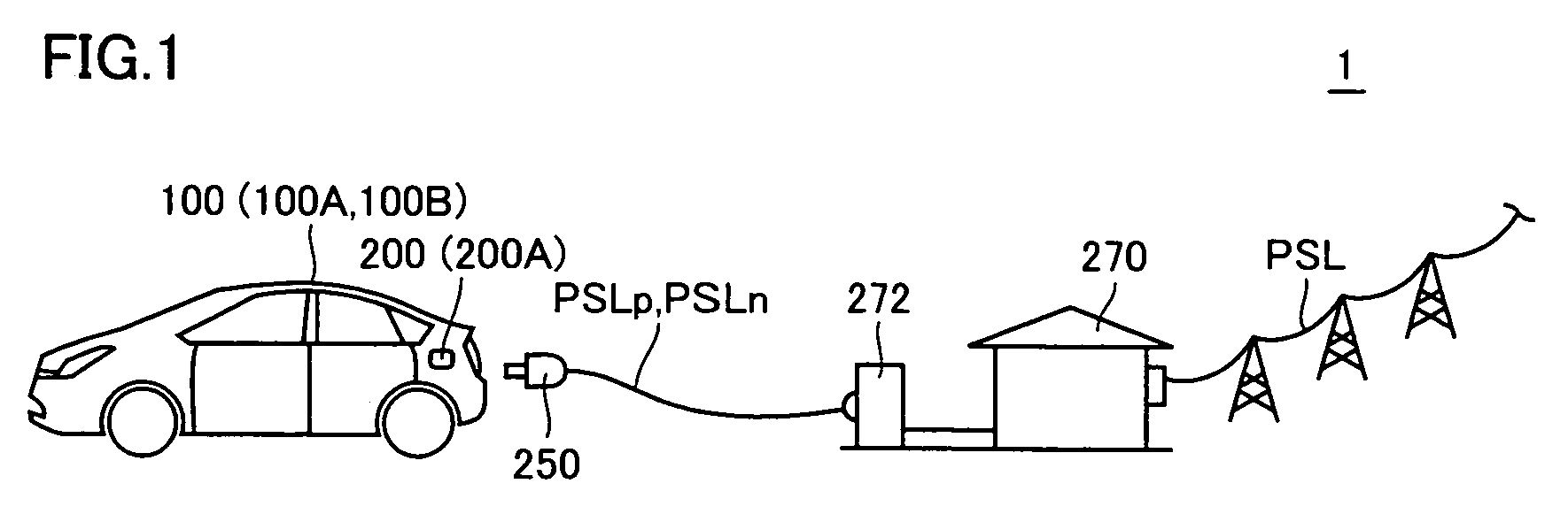
[0032]In an embodiment of the present invention described below, description will be made on an electric-powered vehicle 100 identified as a hybrid vehicle, as an example. However, the embodiment of the present invention is not limited thereto. In the present specification, the electric-powered vehicle is a generic term used to refer to a vehicle mounted with a power storage device and capable of generating driving force for traveling purpose by electric power supplied from the relevant power storage device, and includes an electric vehicle, a fuel-cell vehicle, and the like, in addition to the hybrid vehicle.

[0033]Electric-powered vehicle (hereinafter also referred to as vehicle) 100 according to a first embodiment of the present invention is mounted with an engine, and an electric motor that is rotatably driven by electric power supplied from a mounted power storage device, and achieves high fuel consumption efficiency by allowing each of the engine and the electric motor to gener...

second embodiment

[0098]In the first embodiment of the present invention described above, illustration has been made on the configuration that uses light to indicate the position of the charging port to the user. In contrast, in a second embodiment of the present invention, description will be made on a configuration that uses a sound to indicate the position of the charging port.

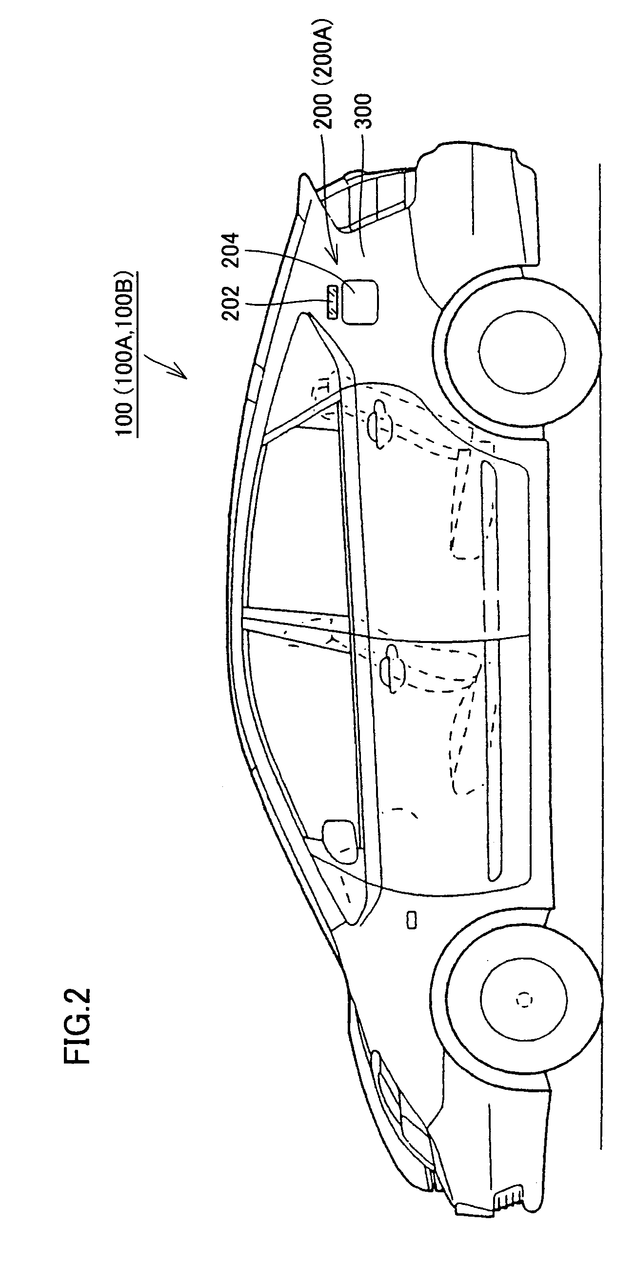
[0099]A system for externally charging an electric-powered vehicle 100A according to the second embodiment of the present invention, a position where a charging port 200A is disposed, and the like, are the same as those in FIG. 1 and FIG. 2, and thus the detailed description thereof will not be repeated.

[0100]FIG. 8A and FIG. 8B are external views of charging port 200A and its surroundings according to the second embodiment of the present invention. FIG. 8A shows an opened state of lid portion 204, while FIG. 8B shows a closed state of lid portion 204.

[0101]With reference to FIG. 8A and FIG. 8B, charging port 200A according ...

second embodiments

Modification of First and Second Embodiments

[0124]For notifying the user of the position of the charging port, description has been made on the configuration in which light-emitting unit 202 provided at a position in proximity to the charging port is lit up in the first embodiment of the present invention, and illustration has been made on the configuration in which sound-generating unit 230 generates a sound (indicating sound) in the second embodiment of the present invention.

[0125]Further, in the first embodiment of the present invention, illustration has been made on the configuration in which light-emitting unit 202 is not lit up if the illuminance around vehicle 100 is sufficiently high. In such a case, however, a sound (indicating sound) may be generated from sound-generating unit 230.

[0126]In other words, to indicate the position of the charging port, both of light-emitting unit 202 and sound-generating unit 230 may be provided, and illuminance around the vehicle may be detec...


PUM


Abstract

A communication unit (32) periodically transmits a request signal toward a prescribed range. When a transmitter (30) exists in the range where the request signal can be received, it sends identification information in a responsive manner. A comparison ECU (48) compares the identification information provided from the communication unit (32) with a predetermined value, and if both of them match with each other, notifies a matching notification to a power source management ECU (44). On receipt of the matching notification from the comparison ECU (48), the power source management ECU (44) notifies a lighting-up request for providing an instruction for lighting-up of a light-emitting unit (202) to a body ECU (46). Upon receipt of the lighting-up request, the body ECU (46) activates a lighting-up command LON. As a result, the light-emitting unit (202) is lit up and notifies a user of the position of a charging port.

Description

TECHNICAL FIELD[0001]The present invention relates to a vehicle capable of utilizing electric power supplied from an external power source.BACKGROUND ART[0002]A so-called electric-powered vehicle such as an electric vehicle, a hybrid vehicle, or a fuel-cell vehicle is mounted with a power storage device made of a secondary battery, a capacitor, or the like, and travels by using driving force generated by electric power stored in the relevant power storage device.[0003]An electric vehicle does not have an electric power-generating mechanism configured with an engine, and thus it has conventionally been required to store electric power to be used for traveling in the power storage device mounted thereon, from an external power source such as a commercial power source. In addition, as to an electric-powered vehicle such as a hybrid vehicle or a fuel-cell vehicle, which has an electric power-generating mechanism, there has also been proposed a technique of charging the power storage dev...

Claims


Application Information

Patent Timeline
Patent Type & Authority Patents(United States)
IPC IPC(8): B60Q1/00B60L50/15B60L50/16
CPCB60K1/04B60L11/14B60L11/1812B60L11/1814B60L11/1818B60L11/1838B60L15/007B60Q9/00B60L11/123Y02T10/7291B60L2220/54B60L2230/16B60L2240/665B60L2270/36Y02T10/6217Y02T10/6269Y02T10/641Y02T10/7005Y02T10/7077Y02T10/7088Y02T90/121Y02T90/127Y02T90/128Y02T90/14Y02T90/16Y02T90/163B60L53/16B60L53/22B60L50/61B60L50/16B60L53/24B60L53/60B60L53/305Y02T10/62Y02T10/64Y02T10/7072Y02T10/72Y02T90/12Y02T10/70
Inventor SUZUKI, NAOTONAKASHIMA, MOTOHIRO
Owner TOYOTA JIDOSHA KK
Learn More