Synchronous pull device for slide cover mechanism

a pull device and slide cover technology, applied in the direction of door/window fittings, wing accessories, instruments, etc., can solve the problems of affecting the stability of the slide cover, the movable system is very likely to be biased, and the slide cover cannot be moved without any possibility of movement, so as to achieve smooth slide and stable slide

Active Publication Date: 2013-08-13
FIRST DOME
View PDF4 Cites 2 Cited by
  • Summary
  • Abstract
  • Description
  • Claims
  • Application Information

AI Technical Summary

Benefits of technology

[0008]It is therefore a primary object of the present invention to provide a synchronous pull device for slide cover mechanism. With the synchronous pull device, the slide cover can still stably and smoothly slide without deflection even under one-side lateral push force.
[0009]It is a further object of the present invention to provide the above synchronous pull device for slide cover mechanism, which has a simplified structure and is easy to assemble. Therefore, the manufacturing cost of the slide cover is lowered to promote the competitive ability of the product.

Problems solved by technology

However, such structure can be hardly applied to a large-size electronic product such as a laptop computer or a tablet computer.
When applying a push force to one single side of the movable system, the movable system is very likely to be biased.
In some more serious cases, the movable system may be stuck with no possibility of moving.
Moreover, it is hard to assemble the elastic members with the driven components.
Also, elastic fatigue of the elastic members tends to take place after a period of use.
This will lead to unsmooth operation of the slide cover.

Method used


Image

  • Synchronous pull device for slide cover mechanism
  • Synchronous pull device for slide cover mechanism
  • Synchronous pull device for slide cover mechanism

Examples


Embodiment Construction

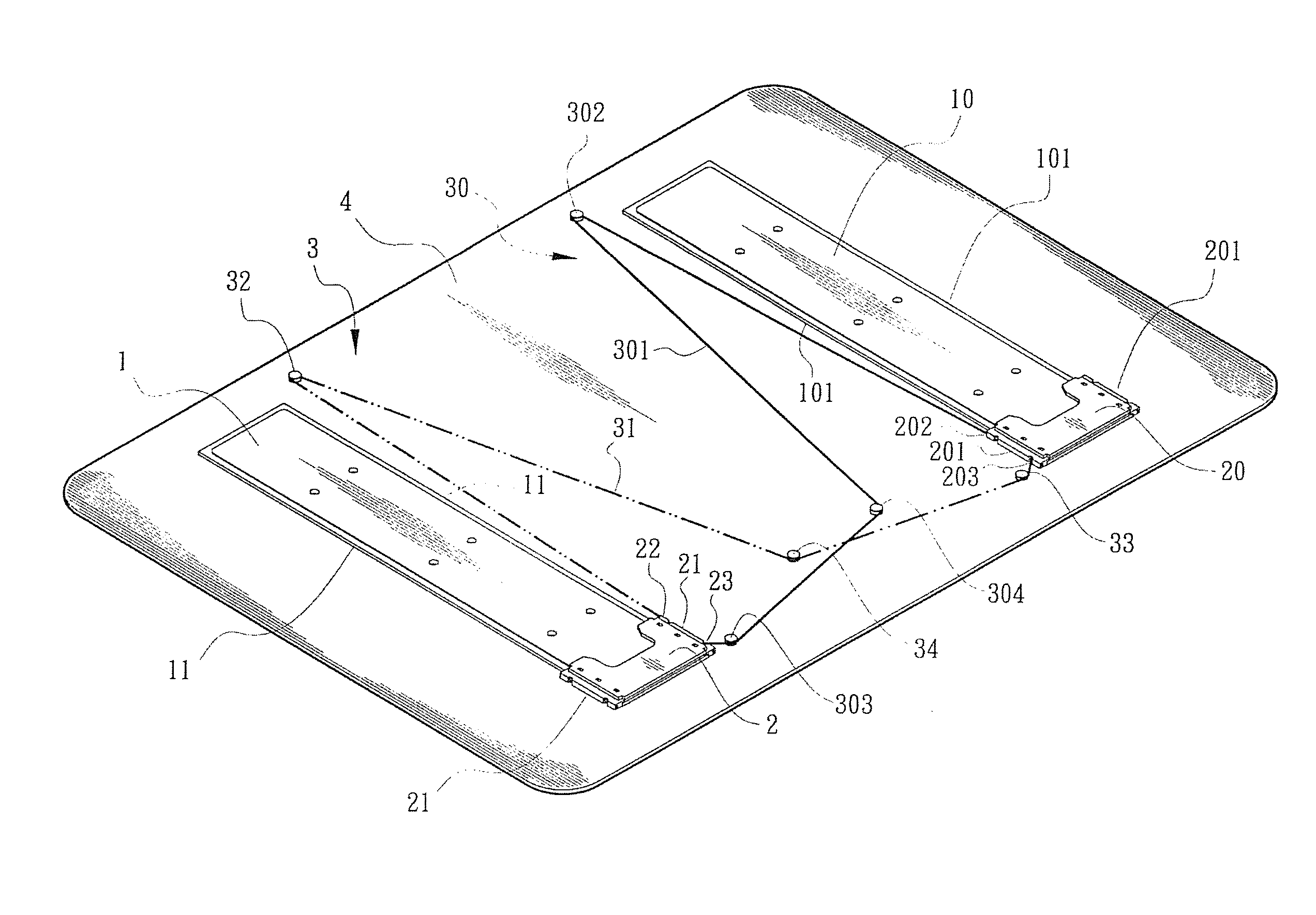
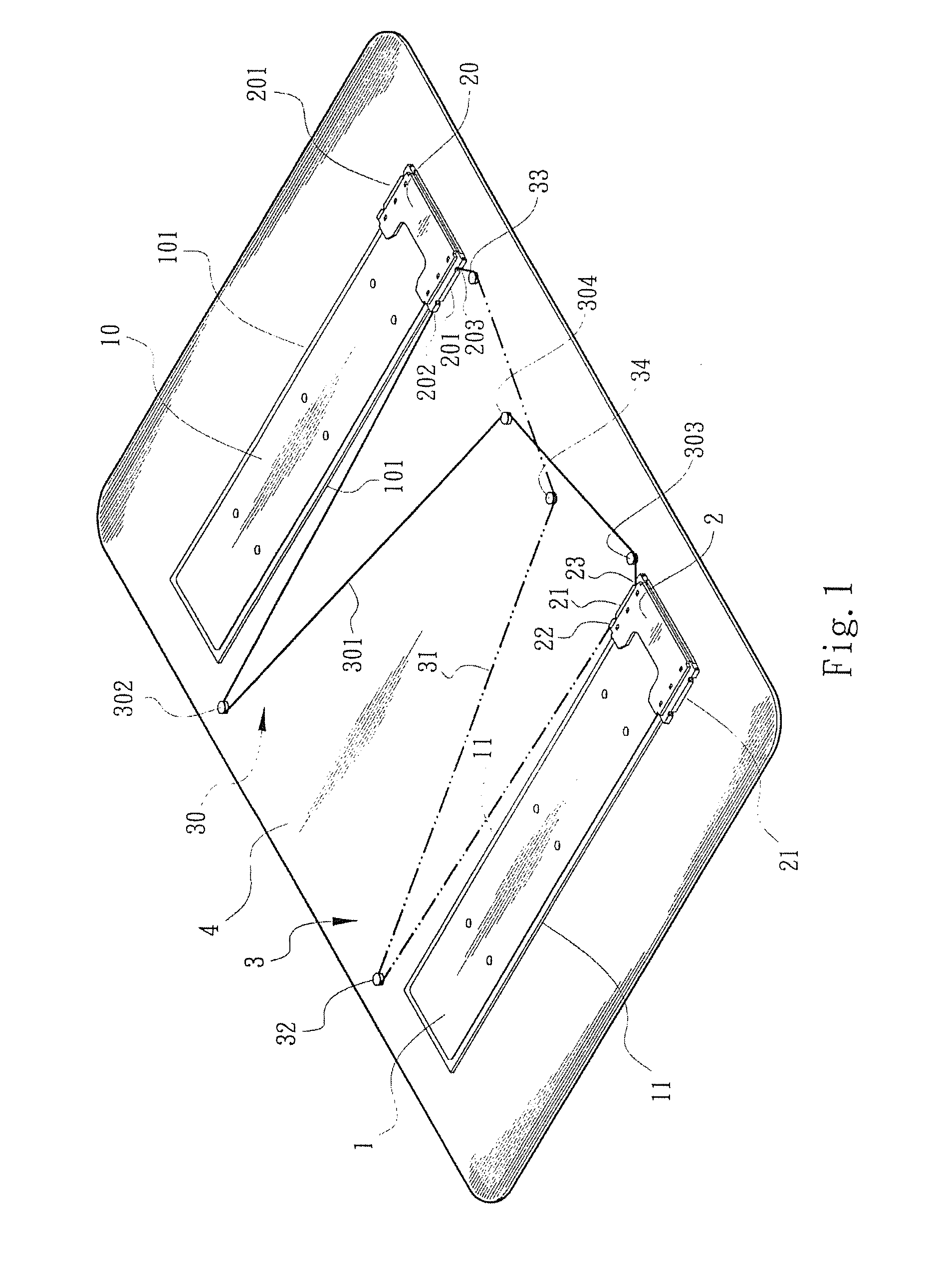
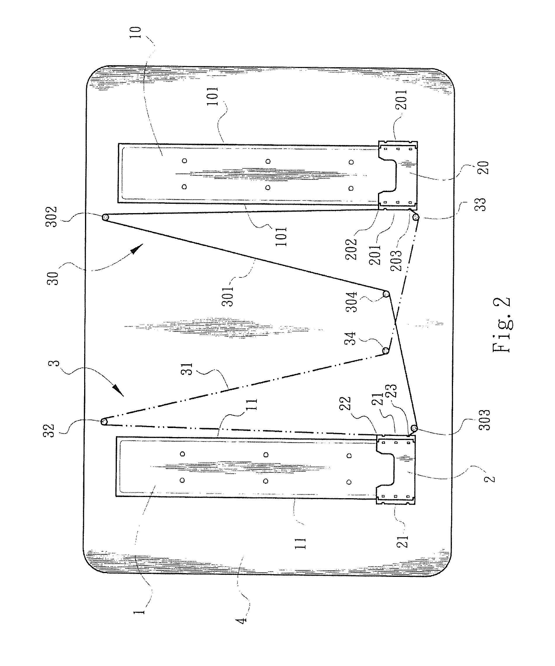
[0018]Please refer to FIGS. 1 to 3. The present invention includes two guide members 1, 10, two slide seats 2, 20 and two pull assemblies 3, 30. The guide members 1, 10 are oppositely side by side arranged on a base seat 4 (preferably in parallel to each other). The base seat 4 is connectable with a slide member (such as a slide cover). In practice, the guide members 1, 10 can be directly disposed on the slide member. At least one slide guide section 11, 101 is disposed on each of the guide members 1, 10. Preferably, each of the guide members 1, 10 has two slide guide sections 11, 101 on two sides. The slide seats 2, 20 are formed or arranged on a relative slide member (such as a main body of an electronic device). At least one low-friction slide jacket section 21, 201 is disposed on one side of each of the slide seats 2, 20. Preferably, each of the slide seats 2, 20 has two slide jacket sections 21, 201 on two sides. The slide jacket sections 21, 201 are slidably connected with the...


PUM


Abstract

A synchronous pull device for slide cover mechanism includes two guide members, two slide seats and two pull assemblies. Slide guide sections are disposed on each guide member, whereby the slide seats can slide along the slide guide sections. First connection ends and second connection ends are respectively disposed on opposite sides of the slide seats. Each pull assembly includes at least two idlers, a middle idler and a pull cord. The two idlers are positioned beside two different ends of two different slide guide sections on opposite sides of the two guide members. The middle idlers are disposed between the two guide members near two ends of the slide guide sections. Each pull cord sequentially goes from the first connection end of one of the slide seats through one idler, the middle idler and the other idler to connect with the second connection end of the other slide seat.

Description

BACKGROUND OF THE INVENTION[0001]1. Field of the Invention[0002]The present invention relates generally to asynchronous pull device for slide cover mechanism, and more particularly to a pull device for slide cover mechanism, which is able to provide stable driving force for the slide cover. With the synchronous pull device, the slide cover can be stably operated without deflection.[0003]2. Description of the Related Art[0004]Various slide cover structures have been developed and applied to different electronic devices to catch up the trend of product design and protect the panels of the electronic devices. For example, Taiwanese Patent Publication No. M392525 discloses a slide cover assembly and a slide cover electronic device. The slide cover assembly is disposed between the cover body and the main body of the electronic device. The slide cover assembly includes a support board connected with the cover body and a link board connected with the main body. A slide block is disposed in...

Claims


Application Information

Patent Timeline
Patent Type & Authority Patents(United States)
IPC IPC(8): H04M1/00H04M9/00
CPCG06F1/1624H04M1/0237E05Y2201/646E05Y2201/668
Inventor HSU, AN SZUKUO, YUNG SHENG
Owner FIRST DOME
Why Eureka
Try Eureka