Image forming apparatus having mechanism for placing fixing unit in nip relaxed state

a technology of fixing unit and forming apparatus, which is applied in the direction of electrographic process apparatus, instruments, optics, etc., can solve the problem of recording sheet jamming in the section between the heating member and the recording sheet, and achieve the effect of smooth clearing

Active Publication Date: 2013-08-13
BROTHER KOGYO KK
View PDF30 Cites 0 Cited by
  • Summary
  • Abstract
  • Description
  • Claims
  • Application Information

AI Technical Summary

Benefits of technology

[0010]In view of the above difficulties, the present invention is advantageous in that an image forming apparatus, which is smaller in size of a nip-relaxing mechanism in a fixing unit, and in which nipping condition in the fixing unit can be smoothly cleared, is provided.

Problems solved by technology

Whilst the recording sheet passes through the narrow nipping section, in which the heating member and the pressing member are in close contact with each other, the recording sheet may jam in the section between the heating member and the pressing member in various reasons.

Method used


Image

  • Image forming apparatus having mechanism for placing fixing unit in nip relaxed state
  • Image forming apparatus having mechanism for placing fixing unit in nip relaxed state
  • Image forming apparatus having mechanism for placing fixing unit in nip relaxed state

Examples


Embodiment Construction

[0026]Overall Configuration of the MFP

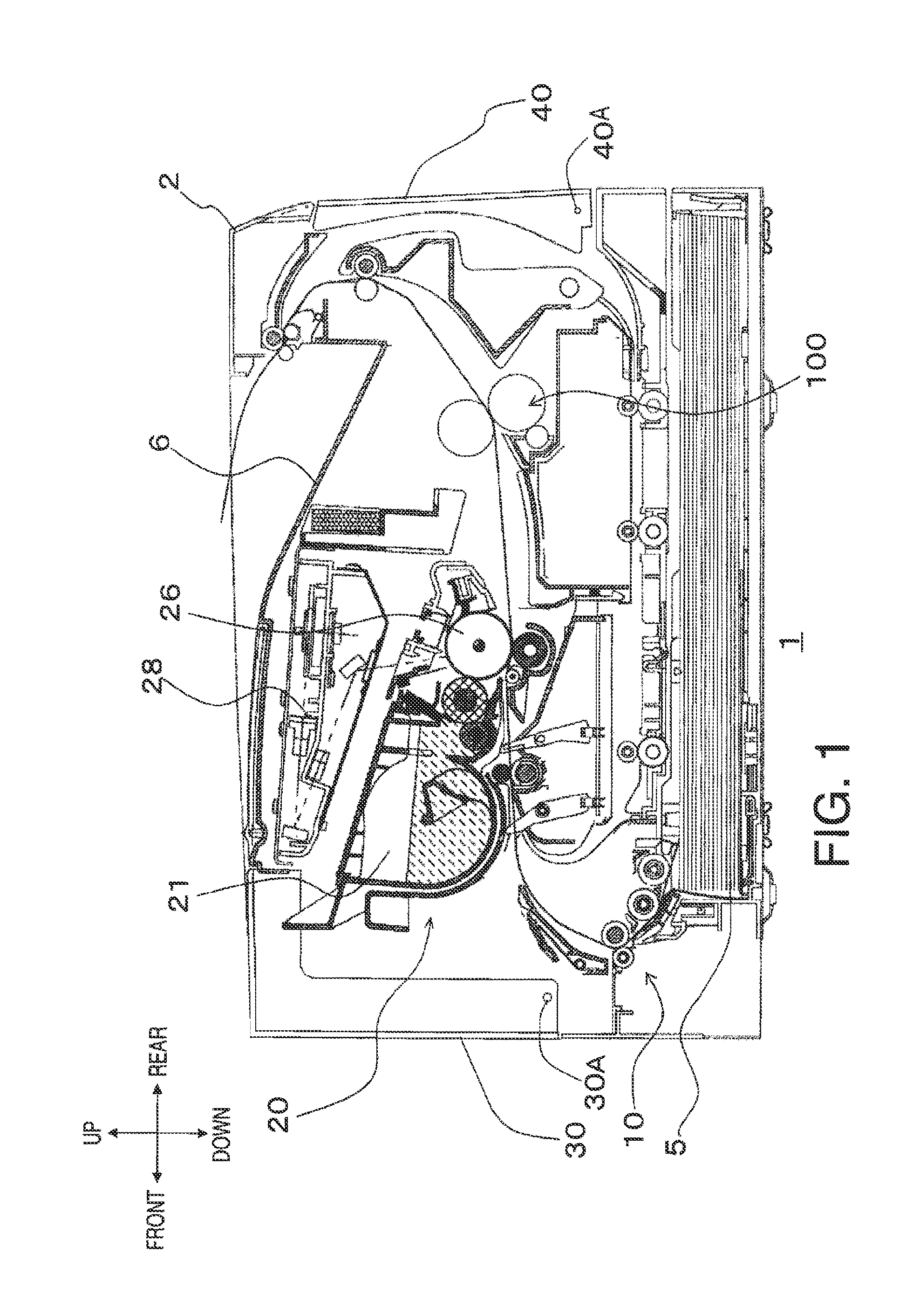
[0027]Hereinafter, embodiments of the present invention will be described with reference to the accompanying drawings. The printer 1 is an image forming apparatus to form an image on a recording sheet, having a sheet-feed tray 5, a sheet conveyer 10, an image forming unit 20, a fixing unit 100, and a discharge tray 6. Recording sheets stored in the sheet-feed tray 5 are picked up one-by-one by the sheet conveyer 10 and conveyed to the image forming unit 20, in which a toner image is formed and transferred onto the recording sheet. The recording sheet with the transferred toner image is further carried to the fixing unit 100, in which the toner image is fixed on the recording sheet, and ejected out of the printer 1. The ejected recording sheet is settled in the discharge tray 6.

[0028]In the description below, directions concerning the printer 1 will be referred to based on a user's position to use the printer 1. That is, a viewer's left-hand side...


PUM


Abstract

An image forming apparatus is provided. The image forming apparatus includes an image forming unit, a door to cover an opening in a chassis, a fixing unit, a frame, a linear motion member to linearly move along with the door, a guiding member to guide the linear motion member to move linearly, a coupler assembly to couple the door with the linear motion member and move the linear motion member, and a manipulation member being movable according to movement of the linear motion member. The linear motion member includes a contact portion, with which the manipulation member comes in contact along an intersecting direction. The guiding member includes a slider plane to slidably support the linear motion member. The linear motion member is slidably supported by the slider plane of the guiding member at a surface which is on an opposite side from the surface having the contact portion.

Description

CROSS REFERENCE TO RELATED APPLICATION[0001]This application claims priority from Japanese Patent Application No. 2010-220564, filed on Sep. 30, 2010, and Japanese Patent Application No 2011-035487, filed on Feb. 22, 2011, the entire subject matters of which are incorporated herein by reference.BACKGROUND[0002]1. Technical Field[0003]An aspect of the present invention relates to an image forming apparatus having a nip-relaxing mechanism, which can clear or relax a nipping condition in a fixing unit in cooperation of an opening motion of a cover of a chassis.[0004]2. Related Art[0005]An image forming apparatus to form an image in toner in an electrophotographic method is often provided with a fixing unit, which fixes the toner image transferred onto a recording sheet thereat by, for example, pressure and heat. The fixing unit includes a heating member (e.g., a heat roller) and a pressing member (e.g., a pressure roller), which are arranged to be in close contact with each other and i...

Claims


Application Information

Patent Timeline
Patent Type & Authority Patents(United States)
IPC IPC(8): G03G15/16
CPCG03G21/1633G03G21/1647G03G15/2035G03G2221/1654G03G2221/1639
Inventor WANG, WEI MING
Owner BROTHER KOGYO KK
Why Eureka
Try Eureka