Oil tank reinforcement core solder filling machine

A technology for strengthening cores and oil tanks, applied in the field of oil tank processing, can solve the problems of excessive solder and difficult control of filling volume, and achieve the effects of improved utilization, light weight, and thorough cleaning

Active Publication Date: 2016-06-15
ZHEJIANG OCEAN UNIV
View PDF12 Cites 0 Cited by
  • Summary
  • Abstract
  • Description
  • Claims
  • Application Information

AI Technical Summary

Problems solved by technology

[0003] The invention provides a height-adjustable oil tank reinforcement core solder filling machine which is easy to control the amount of solder uploaded and has less solder adhesion in the invalid area. The problem of too much solder

Method used


Image

  • Oil tank reinforcement core solder filling machine
  • Oil tank reinforcement core solder filling machine
  • Oil tank reinforcement core solder filling machine

Examples


Embodiment 1

[0052] Embodiment one, see Figure 5 , The oil tank reinforced core solder filling machine used in the present invention includes a frame 1, a solder filling mechanism 2, a material feeding tank 4, a solder flow controller 5 and a solder cleaning and recovery mechanism 6 arranged on the frame.

[0053] The frame 1 is provided with lifting feet 11 . This facilitates high-level docking with adjacent equipment during assembly-line operations.

[0054] The solder filling mechanism 2 includes a first oil tank reinforcing core support hole 21 , a solder injection cylinder 22 , a first cylinder 23 , a pressing plate 24 , a second cylinder 25 and two first lifting guide rods 26 . The support hole 21 of the first oil tank reinforcing core is fixed on the frame 1 . The solder injection cylinder 22 is located below the support hole 21 of the first oil tank reinforcement core and its upper end is connected with the support hole 21 of the first oil tank reinforcement core. The first cyl...

Embodiment 2

[0069] Embodiment two, the difference with embodiment one is:

[0070] see Figure 9, The oil tank reinforcement core solder filling machine is also provided with an oil tank reinforcement core transfer mechanism 9 . The oil tank reinforcing core transfer mechanism 9 includes a swing arm 91 , a suction cup 92 and a driving device 93 . One end of the swing arm 91 is connected with the suction cup 92 , and the other end is connected with the driving device 93 . The driving device 93 is a motor. The centerline of the first oil tank reinforcement core support hole 21 is parallel to the centerline of the second oil tank reinforcement core support hole swing arm 91 . The centerline of the swing axis of the swing arm 91 is perpendicular to the plane defined by the centerline of the support hole of the first oil tank reinforcement core and the centerline of the swing arm of the second oil tank reinforcement core support hole. The distance between the centerline of the swing axis o...

Embodiment 3

[0085] Embodiment three, see Figure 16 , the difference with the second embodiment is: the corrosive liquid storage tank 34 is provided with a wave-dissipating plate 341 floating on the corrosive liquid 37 in the corrosive liquid storage tank. The shell 351 passes through the wave breaking plate 341 in a liftable manner along the up and down direction. The peripheral surface of the wave breaking plate 341 abuts against the side wall of the corrosive liquid storage tank 34 .


PUM


Abstract

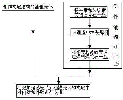
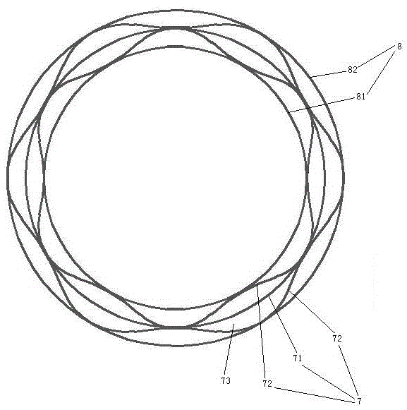
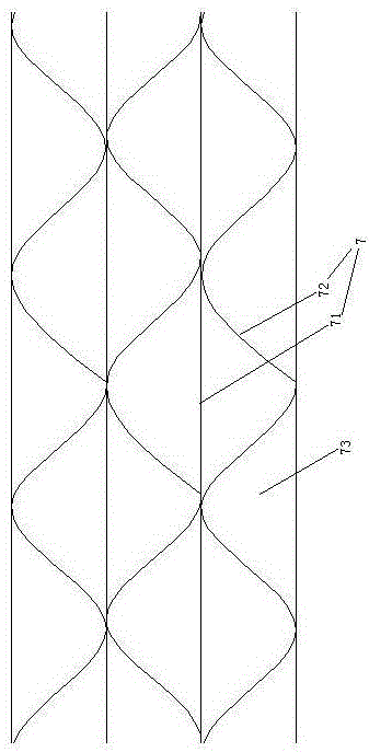
The invention relates to the field of oil tank processing, and solves the problems that the filling amount is difficult to control, a large quantity of welding fluxes are attached to an ineffective region and an oil tank is heavy in an oil tank reinforcement core welding flux filling process. An oil tank manufacturing method comprises an oil tank reinforcement core manufacturing technology; the technology comprises the steps of stacking a flat belt and a corrugated belt in a staggered manner, and forming a channel between the flat belt and the corrugated belt; filling the channel with a welding flux; welding the flat belt and the corrugated belt together through the welding flux. An oil tank reinforcement core welding flux filling machine which can easily control a welding flux loading amount, has a small quantity of welding fluxes attached to the ineffective region and is adjustable in height comprises a stander provided with lifting legs, a welding flux filling mechanism, a material loading tank and a welding flux cleaning and recycling mechanism; the welding flux filling mechanism comprises a first oil tank reinforcement core supporting hole, a welding flux injection cylinder, a material push head and a first cylinder; the material loading tank is connected with the welding flux injection cylinder; the welding flux cleaning and recycling mechanism comprises recycled material barrels, an air extractor, a second oil tank reinforcement core supporting hole, an air flow adjustment plate and a third cylinder.

Description

technical field [0001] The invention relates to the field of oil tank processing, in particular to an oil tank reinforcement core solder filling machine and an oil tank manufacturing method. Background technique [0002] The tank body of existing oil cylinder is made by steel plate. In Chinese Patent No. 2010106019906, the publication date is July 11, 2012, and the patent document titled "Oil Tank" discloses a patent of a prior structure. The wall of the existing oil tank is a solid structure, and in order to improve the strength of the tank body, it is realized by increasing the wall thickness of the tank body. Therefore existing oil tank has the deficiency of heavy weight. Contents of the invention [0003] The invention provides a height-adjustable oil tank reinforcement core solder filling machine which is easy to control the amount of solder uploaded and has less solder adhesion in the invalid area. The problem of too much solder. [0004] The invention also provi...

Claims


Application Information

Patent Timeline
Patent Type & Authority Patents(China)
IPC IPC(8): B23K37/00B23K31/02
CPCB23K31/02B23K37/00
Inventor 高良军杨浩文建军杨淑清周领
Owner ZHEJIANG OCEAN UNIV
Why Eureka
Try Eureka