Apparatus having at least one separating knife in cotton carding machine, dust-colecting machnie or the like

A technology for separating knives and preparation machines, used in deburring devices, textile and papermaking, fiber processing, etc., to solve the problems of complicated removal, machine interruption, etc.

Inactive Publication Date: 2009-01-21
TRUETZSCHLER GRP SE
View PDF7 Cites 0 Cited by
  • Summary
  • Abstract
  • Description
  • Claims
  • Application Information

AI Technical Summary

Problems solved by technology

This complicates cleanup and can cause the machine to stop working
Another disadvantage is that the impurities fall in a diffuse manner and the entire lower space of the machine must therefore be cleaned

Method used


Image

  • Apparatus having at least one separating knife in cotton carding machine, dust-colecting machnie or the like
  • Apparatus having at least one separating knife in cotton carding machine, dust-colecting machnie or the like
  • Apparatus having at least one separating knife in cotton carding machine, dust-colecting machnie or the like

Examples


Embodiment Construction

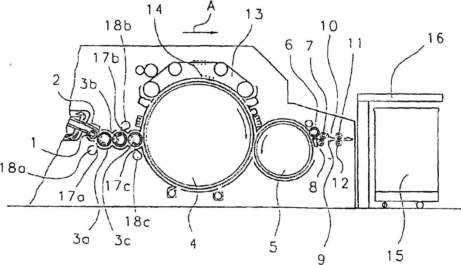
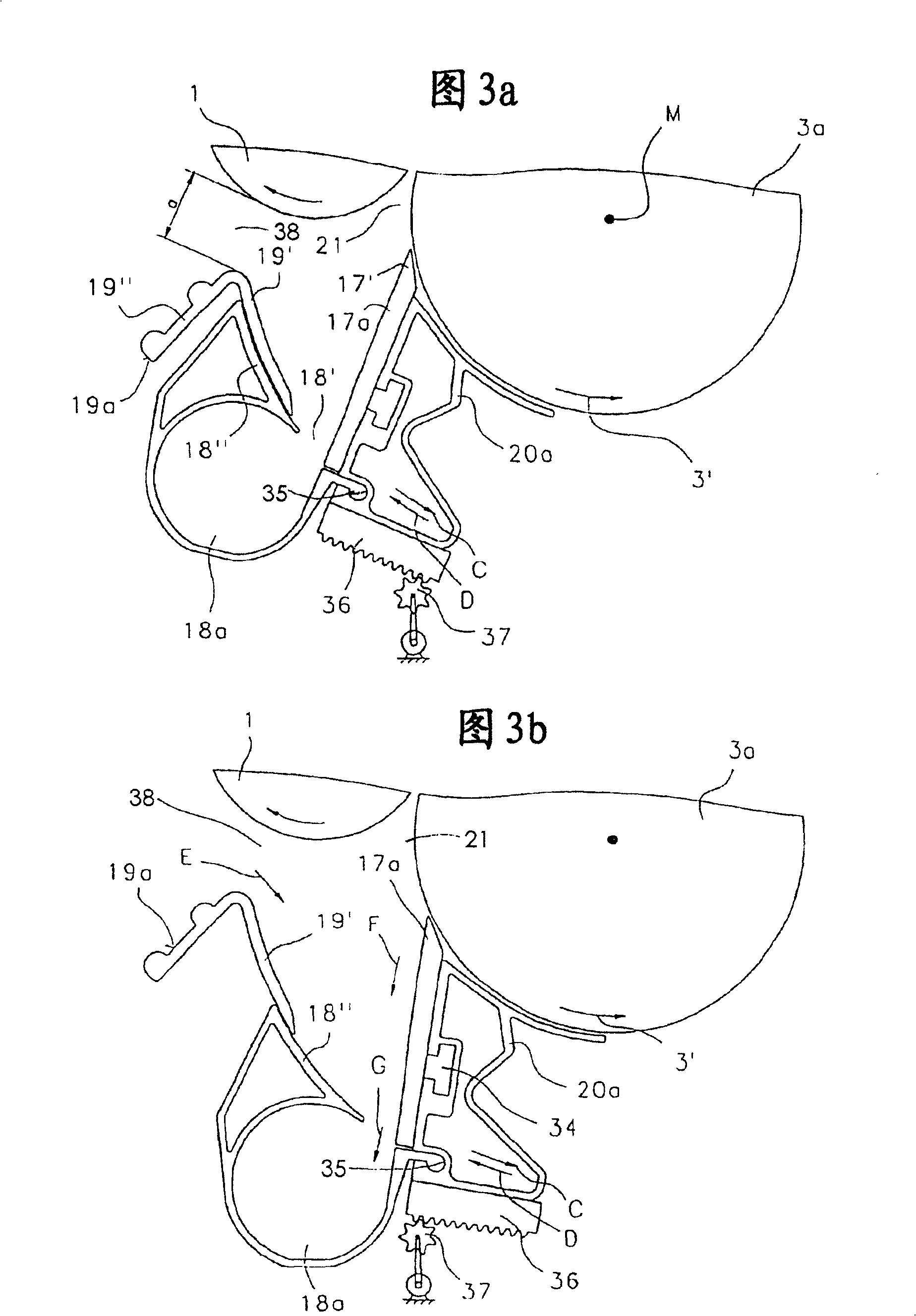
[0011] figure 1 shows a carding machine, such as a - High performance card DK903 with a feed roller 1, feed table 2, licker-in rollers 3a, 3b, 3c, cylinder 4, doffer 5, stripping roller 6, rollers 7, 8, web guiding elements 9 , Guide bar horn head 10, conveying rollers 11, 12, rotary carding flat 13 with cloth carding jack 14, bar can 15 and coiler 16. The direction of rotation of the roller is indicated by a curved arrow, and the direction of operation is indicated by the letter A. The licker-in rollers 3a, 3b and 3c are each connected to a separating knife 17a, 17b and 17c having discharge hoods 18a, 18b, 18c, respectively. In the region of the outlet chambers 18a, 18b, 18c, according to FIGS. 3a, 3b, guide elements 19a, 19b and 19c are respectively arranged. The separating knives 17a, 17b and 17c and the discharge hoods 18a, 18b and 18c are respectively mounted on a movable support 20a, 20b and 20c (see FIGS. 3a, 3b).

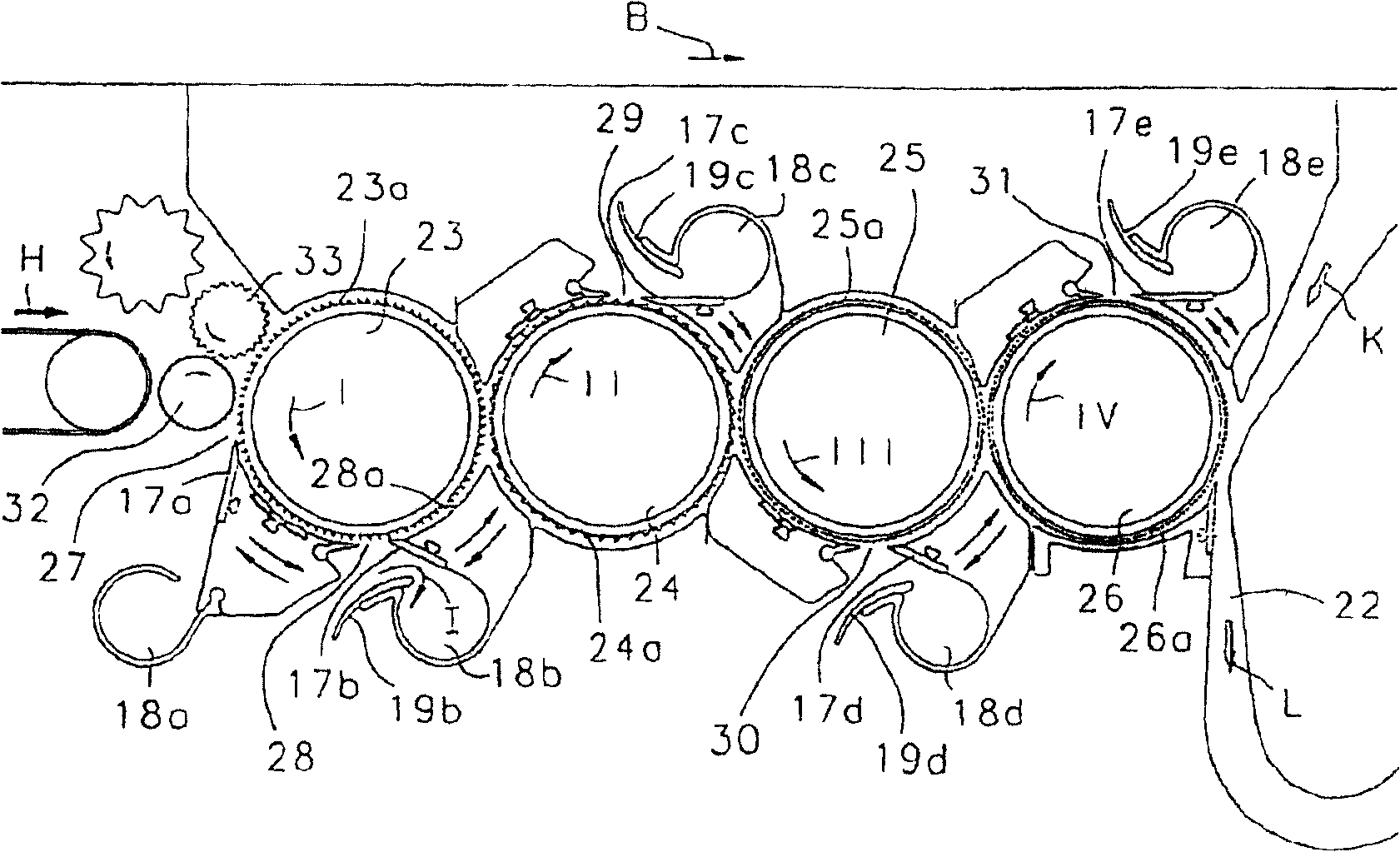
[0012] according to figure 2 , the dedusting de...


PUM


Abstract

A device with at least one impurity separation knife (17a) on a spinning preparation machine, especially a cotton carding machine, a dust collector or similar machinery, which is connected to a wrapping roller 3a, in which the separation knife (17a) is installed On a support (20) which is movable parallel to the circumference of the roller, the distance between the separating blade (17a) and a fixed position counterpart element adjacent to the separating opening is variable. Even in the case where the position of the separation knife (17a) is changed, in order to uniformly remove impurities and uniformly supply air so that they enter a discharge chamber (18a), the separation knife (17a) is connected to a discharge chamber (18a), and the discharge chamber Mounted on the support (20), the discharge chamber (18a) cooperates with a fixed position guide element (19a) that enables the separated impurities and / or air to be guided into the discharge chamber (18a) in the opening (18′).

Description

technical field [0001] The invention relates to a device on a spinning preparation machine (cotton carding machine, dedusting machine or similar) with at least one separating knife connected to a wrapping roll (for example a licker-in roll or similar), wherein the separating knife is mounted on a support movable parallel to (concentric with) the circumference of said roller and wherein the distance between the separating blade and a fixed position counter element adjacent to the separating opening is variable . Background technique [0002] In a known device (EP0618318), the impurities separated by the separating knives fall downwards into the space below the rollers, where they are to be removed. This complicates cleanup and can cause the machine to stop working. A further disadvantage of this is that the impurities fall in a diffuse manner and therefore the entire machine underside has to be cleaned. As a result, impurities and air flow swirl around. Contents of the i...

Claims


Application Information

Patent Timeline
Patent Type & Authority Patents(China)
IPC IPC(8): D01G15/34
CPCD01G15/34
Inventor 马库斯·施密茨
Owner TRUETZSCHLER GRP SE
Why Eureka
Try Eureka