Fixing device

a fixing device and a technology for forming apparatuses, applied in the direction of instruments, electrographic process apparatus, optics, etc., can solve the problems of increasing the size of the image forming apparatus, increasing the necessary electric power, and not being able to achieve a good fixing state

Inactive Publication Date: 2013-08-13
CANON KK
View PDF6 Cites 6 Cited by
  • Summary
  • Abstract
  • Description
  • Claims
  • Application Information

AI Technical Summary

Benefits of technology

[0021]A principal object of the present invention is to provide a fixing device capable of obtaining a good fixing state even in the case where an amount of a toner in layer is small.

Problems solved by technology

In order to transmit a sufficient heat quantity, the pair of rollers can be increased in diameter or a temperature of a fixing roller can be increased but there are many increasing disadvantages such that the image forming apparatus is increased in size and that necessary electric power is increased.
Further, it can also be considered that a pressure is increased but an increase in fixing nip width, between the pair of rollers, with the pressure is not large and therefore so much effect cannot be expected.
However, a new problem arises in that the unfixed toner image with a small toner amount is fixed by using the conventionally proposed heat-fixing method to output the high-quality image with the low toner consumption.
That is, an image quality of a single color and an image quality of secondary color or multi-order color cannot be maintained simultaneously.
However, it has been found that the thus-constituted inner nip pressure distribution is not suitable for the case of a small toner.
However, in the case where the toner image of the single color is formed in the single layer, the toner is excessively melted.
As a result, such a phenomenon, that the toner is dropped from fibers of the recording material surface to expose a texture of paper, which is called a “see-thru” phenomenon, or such a phenomenon that a surface property of the toner image is impaired is caused to occur.

Method used


Image

  • Fixing device
  • Fixing device
  • Fixing device

Examples


embodiment 1

[Embodiment 1]

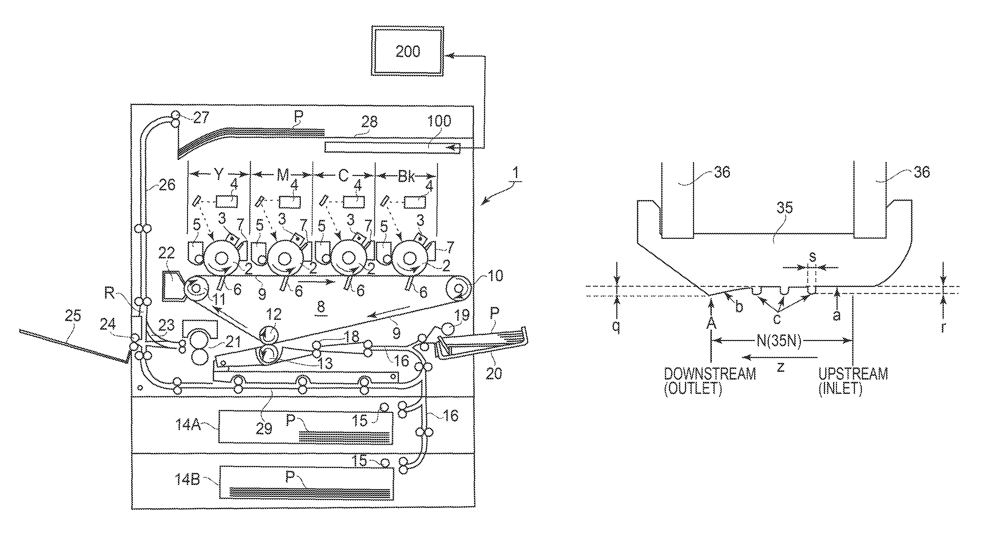
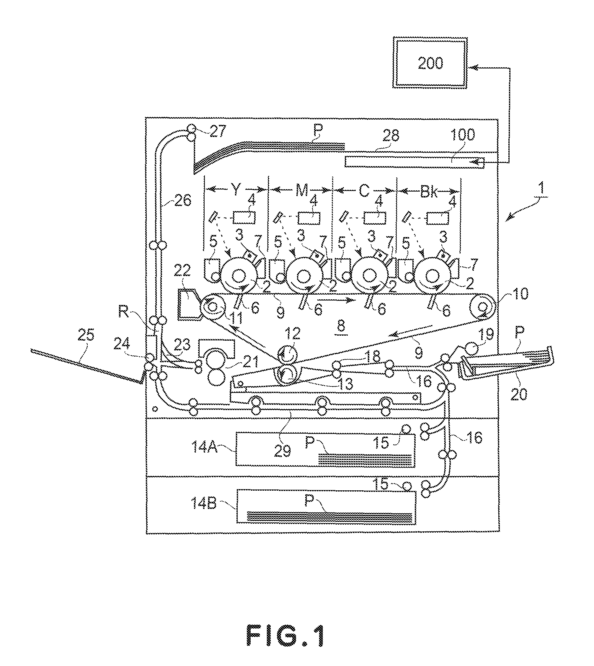
[0059]FIG. 1 is a schematic longitudinal view showing a general structure of an electrophotographic color printer 1 as an example of an image forming apparatus in which a fixing device 21 according to the present invention is mounted.

[0060]This printer 1 performs an image forming operation depending on image information inputted from a device 200 communicatably connected with a control circuit portion (control board: CPU) 100, thus being capable of forming a full-color image on a sheet-like recording material P and then outputting the full-color image as a hard copy.

[0061]The device 200 is a computer, an image reader, a facsimile machine or the like. The control circuit portion 100 as the control portion sends signals to and receives signals from the external host device 200. Further, the control circuit portion 100 sends signals to and receives signals from various devices for image formation on the printer side to manage image forming sequence control.

[0062]On the re...

embodiment 2

[Embodiment 2]

[0281]In Embodiment 2, by using the toner having the melt viscosity characteristic as shown in FIG. 33, a verification of a relationship among the pressure, the single-color toner image density and the secondary color toner chroma was conducted in the same manner as in Embodiment 1. The softening temperature Ts and the incipient fluidization temperature Tfb of the toner measured by using the follow tester were as follows.[0282]Ts: 65.0° C.[0283]Tfb: 82.3° C.

[0284]Further, in this embodiment, the toner had the specific gravity ρ of 1.1 (g / cm3) and the weight-average particle size L of 6.0 (μm). As the recording material, the sheet (“CS814” (81 g / m2) mfd. by Nippon Paper Group Corp.) was used. Further, the toner amount per unit area of the single-color toner was 0.3 (mg / cm2). This toner amount per unit area was set at the value smaller than that necessary to cover the recording material.

[0285]Further, the fixing device used in this embodiment employed the fixing device c...

embodiment 3

[Embodiment 3]

[0308]In Embodiment 3, a degree of pressure drop in the pressure distribution in the fixing nip and an image property will be described.

[0309]In the fixing nip, the toner temperature is gradually increased and reaches the highest temperature at the outlet portion of the fixing nip. With respect to the toner temperature, by applying a proper pressure at each portion, a good fixing image can be obtained.

[0310]However, when there a portion where the pressure is largely dropped in the fixing nip, the proper toner melting state is impaired and thus the image property is disturbed. Although also described in in Embodiment 1, e.g., as shown in the graphs of FIGS. 19 and 22, in the case where the high pressure state and the low pressure state are compared, the single-color toner spread ratio (amount) and the secondary color toner overlapping ratio are larger in the high pressure state.

[0311]This is because when the pressure is P and the toner viscosity is η, the toner deforma...


PUM


Abstract

A fixing device includes a belt heating a toner image on recording material, a member slidable on the belt inner surface, a pressor pressing the belt against the member to form a recording material nip, and a projection and recess provided on a nip forming surface of the member. When pressure applied when a toner temperature of the toner image reaches a softening temperature T1 (° C.) is P1 (kgf / cm2), pressure applied when the toner temperature reaches an incipient fluidization temperature T2 (° C.) is P2 (kgf / cm2), the toner temperature when P(t) / η(t) wherein η(t)is a toner melt viscosity (Pa·s) and P(t) is a pressure (kgf / cm2) applied with the toner melt viscosity η(t) is maximum is T3 (° C.), and pressure applied when the toner temperature reaches T3 (° C.) is P3 (kgf / cm2), the following relationships are satisfied:0.3<P1 / (P1+P2+P3),  1)0.3<P2 / (P1+P2+P3), and  2)0.2<P3 / (P1+P2+P3)<0.3.  3)

Description

FIELD OF THE INVENTION AND RELATED ART[0001]The present invention relates to a fixing device for fixing an unfixed toner image, by heat-pressing the toner image, formed on a recording material through an image forming process, such as an electrophotographic process, an electrostatic recording process or a magnetic recording process, of a transfer type or a direct type.[0002]An image forming apparatus using the electrophotographic process or the like to obtain a hard copy, such as a copying machine, a facsimile machine or a printer is currently used in various fields with development of its technology and enlargement of market demand. Particularly, in recent years, demands for environmental response and cost reduction are increased, so that a toner consumption reducing technique has become very important. This technique is important also from the viewpoint of reduction in energy generated in a process in which the toner is fixed on the recording material. Particularly, in the image f...

Claims


Application Information

Patent Timeline
Patent Type & Authority Patents(United States)
IPC IPC(8): G03G15/20
CPCG03G15/2039G03G15/2064G03G2215/2025
Inventor TAKEMURA, TAICHI
Owner CANON KK
Why Eureka
Try Eureka